


- 17 -
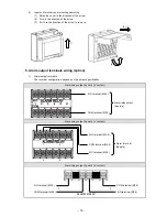
2)
Wiring
Turn OFF the feed power source and the power source for buffer relay before wiring to prevent an electric
shock.
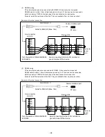
(1) Wire the cable to the load via the buffer relay.
(2) To the alarm output terminals, type O crimp style terminal with insulation sleeve which is connected to
double insulated signal wire should be connected. ( Refer to P13 )
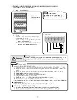
Mechanical relay
‘a’ contact output example
Mechanical
relay ‘c’ contact output example
* N.C terminal is opened on alarm occurrence in opposite way to N.O terminal.
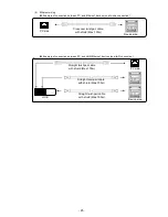
mark on alarm output terminals
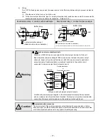
Maximum of 240VAC can be connected to the alarm output terminals of this unit.
Basic insulation (dielectric strength 1390V) is carried out between the alarm output
channels, however, from the malfunction etc. 240VAC may be output to each alarm
output terminals. Double insulation or reinforced insulation to the outside circuit
connected to an alarm output terminal should be set.
A buffer relay power supply is applied to the alarm output terminals after connections
and so creates a risk of electric shock if touched. Terminal cover must be mounted after
connection. Moreover, safety measures to the outside circuit should be set.
Implement safety measures.
The alarm output of the unit may generate output failure with wrong operation, failure,
abnormal input, or others. Double insulation or reinforced insulation in outside circuit side
of all the channels should be set in any system for safety ensuring.
!
!
Caution
!
Warning
: Contact protective element
(Attachment to a side is desirable.)
N.O
COM
b
a
Z
Z
Buffer relay
Recorder
Power
Load
: Contact protective element
(Attachment to a side is desirable.)
Buffer relay
Recorder
Power
Load
Z
Z
N.C
N.O
COM
b
a
240VAC
Max
Load
240VAC
Max
L
oad
※
Recorder
※
Basic insulation between output channels
Double insulation
or
Reinforced insulation


