

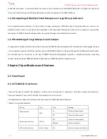
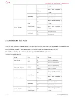
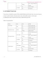


STCS4012 Series Layer 3 Switch Installation Guide
- - 9 - -
www.stephen-tele.com
Chapter 4 Installation
4.1 Hardware Installation
4.1.1 Installing the Switch in 19-inch Standard Cabinet
Take the following steps to install the switch:
Step 1: Check the grounding and stability of the cabinet. Attach the angle iron at both sides of the front or rear panel with screws.
Step 2: Place Switch on a shelf of the cabinet. In accordance with the actual cases, slide switch along the guiding slots of the
cabinet to an appropriate position. Ensure that there is proper clearance between the Switch and the guides.
Step 3: Use screws to attach the angle iron on the fixed cable guides at both sides of the cabinet. Make sure that switch is
securely mounted on the cabinet with the brackets of cabinet slots and the mounting angle iron of the switch.
4.1.2 Installing the switch on the Workbench
If 19-inch standard cabinet is not available, you may simply place the switch on a clean workbench. However, you need to pay
attention to the followings during such operation:
Make sure that the workbench is stable and well grounded.
Leave about 10 centimeters away from the four sides of the switch for heat dissipation.
Do not place heavy objects on top of the switch.
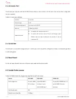
4.2 Connecting Power Cord
Step 1: Connect one end of the ground wire of the chassis shipped with the switch to the grounding screw on the switch rear
panel, and properly ground the other end as near as possible.
Step 2: Plug one end of the power cord to the power socket on the rear panel of the switch chassis, and plug the other end into
the socket of AC power supply.
Step 3: Check whether the power indicator (POWER) on the front panel of the switch is on. On means that the power cord is
correctly connected.


