background image


STCS4012 Series Layer 3 Switch Installation Guide


- - 7 - -                                                                                                                                                                                     

    www.stephen-tele.com 
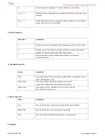
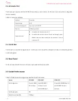
HTTP 

Yes 

CLI 

Yes 

Dimension (L*W *H) 

443mm×360mm×44.5mm 

Working Environment 

0~40 °C 10

90

  non-condensing 

Weight 

<6.5Kg 

Chapter 3 Installation Preparation 

3.1 Precautions 

To avoid any device impairment and bodily injury due to improper use, please follow the precautions listed below: 


Before cleaning the switch, please unplug the switch connector first. Do not clean the switch with wet cloth or with liquid. 


Do not place the switch near water or any damp area. Try as much as possible to prevent water and moisture from entering 

the switch chassis. 


Do not place the switch on the unstable cases or desktop, as the switch might be damaged severely in case of a fall. 


Ensure proper ventilation of the room and keep the switch ventilation hole free of obstruction. 


The switch can operate normally under correct voltage input. Make sure that the operating voltage is consistent with that 

labeled on the switch. 


Do not open the chassis while the switch is in operation to protect the safe of the operator and the switch. 

3.2 Requirements on Environment 

Switch should be used indoors. The following requirements must be met irrespective of whether you install the switch in 19-inch 

standard cabinet or install it directly on the workbench.   


Make sure that enough room is left for the ventilation hole of the switch so as to ensure the heat dissipation of the switch 

chassis. 


Make sure that the drafting and heat dissipation systems of the cabinet and the workbench are good.   


Make sure that the cabinet and the workbench are stable enough to bear the weight of the switch and the accessories. 


Make sure that the cabinet and the workbench are well grounded. 

To ensure normal operation and prolong the service life of the switch, the requirements on the installation site described in the 

following sections must also be met. 

Содержание STCS4012 Series

Страница 1: ...STCS4012 Series Layer 3 Switch Installation Guide www stephen tele com STCS4012 Series Routing Switches Installtion Guide Manual VER 1 0 0 STEPHEN TECHNOLOGIES CO LIMITED ALL RIGHTS RESERVED...

Страница 2: ...e manual is intended for the following readers Network engineers Network administrators Customers who are familiar with network fundamentals Conventions The manual uses the following conventions I Gen...

Страница 3: ...ets For example pop up the New User window Multi level menus are separated by forward slashes For example File Create Folder IV Keyboard operation Format Description Key Press the key with the key nam...

Страница 4: ...tele com Eye catching symbols are also used in the manual to highlight the points worthy of special attention during the operation They are defined as follows Caution Means reader be extremely carefu...

Страница 5: ...Port 5 2 2 Rear Panel 5 2 3 Switch Performance 5 Chapter 3 Installation Preparation 7 3 1 Precautions 7 3 2 Requirements on Environment 7 3 2 1 Temperature Humidity Requirements 8 3 2 2 Laser Safety 8...

Страница 6: ...HIMA has the independent intelligent property STCS4012 Series Routing Switches can provide various routing protocols VLAN management traffic control and Qos guarantee etc and it also provides perfect...

Страница 7: ...re located on the convergence layer and connected to several L2 Ethernet switches such as SPEED S2026 Switch on the downlink and the backbone GE switch via the GE extended port on the uplink In this w...

Страница 8: ...quence 1 AUX port 1 system led indicator 1 Power led indicator 1 pair of AUX Link ACT led indicators in the front panel The table below describes the indicators on the front panel of STCS4012ST Ethern...

Страница 9: ...ibes the indicators on the front panel of STCS4012TF Ethernet Switch Table 2 3 Front panel indicators Indicator Sign State Meaning Power indicator PWR On The switch is powered on Off The switch is pow...

Страница 10: ...h a pair of Modems when connected remotely and the execution of terminal simulator on PC 2 1 5 AUX Port The AUX port is an assistant management port Via this port Users can perform configuration local...

Страница 11: ...for flow shaping and rich scheduling methods Queue Dispatching Methods WRR SP WRR SP Port Convergence Supports FE GE port convergence maximum 32 groups with 8 ports at most in each group Routing Proto...

Страница 12: ...can operate normally under correct voltage input Make sure that the operating voltage is consistent with that labeled on the switch Do not open the chassis while the switch is in operation to protect...

Страница 13: ...eopardize the CMOS circuit of the switch The Higher the temperature is the greater the damage to the switch will be The reliability of the switch will be then seriously affected and its service span w...

Страница 14: ...abinet slots and the mounting angle iron of the switch 4 1 2 Installing the switch on the Workbench If 19 inch standard cabinet is not available you may simply place the switch on a clean workbench Ho...

Страница 15: ...ch at the configuration terminal take the following steps to connect the console cable Step 1 Plug the console cable s DB 9 female connector to the serial port of the PC or the terminal where the swit...

Страница 16: ...r cabling In the case of outdoor cabling check if the socket strip with lightning protection and network port lightning arrester have been connected Chapter 5 Booting and Configuration 5 1 Setting up...

Страница 17: ...to VT100 The specific means is as follow 1 Click Start Program Accessories Communications Hyper Terminal to enter the Hyper Terminal window in which click icon to establish a new connection and the sy...

Страница 18: ...port to be used in HyperTerminal connection 3 Click OK after the serial port is selected and the system will pop up the setting interface of the connecting serial port parameters shown in the followin...

Страница 19: ...4 2 Powering on and Booting After the switch is powered on first run the BOOTROM program and the terminal yields the following output Stable and Portable Route Operating System SPROS Boot Copyright c...

Страница 20: ...Check CPU 198 001512 MHz OK Switch Firmware Init OK Layer 2 Application OK Layer 3 Application OK Entering SPROS Initializing environment Done Loading startup config Done Welcome to SPROS Press Retur...

Страница 21: ...ribed in this document The information provided by this document is believed to be accurate and reliable to the publication date of this document However Stephen Technologies Co LTD assumes no respons...

Отзывы: