


チコーエアーテック株式会社
Copyright CHIKO AIRTEC CO., LTD. 2013
9
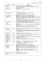
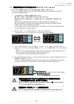
圧力表示切替ランプ
Pressure display lamp change
4
操作
Operation
4.1
電源について
Power supply
本機の電源は、単相電源です。
The power supply is single-phase.
供給電圧の許容範囲は、±
10
%です。
電源コード(コード長さ
3m
)付きです。(アース付プラグ)
The allowable supply voltage range is ±10%.
The power cable of 3 m with a grounding plug is included.
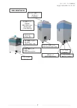
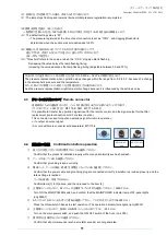
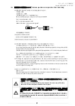
4.2 AT2
パネルについて
(060AT
のみ
)
AT2 panel
(
only 060AT
)
異なった電源で運転されますと、故障の原因になります。
Operating the product with a different power supply may cause a failure.
電圧降下の原因になりますので、タコ足配線にしないで下さい。
(
電圧が降下すると起動時間が長くなります
)
Never adopt star-burst connection that may cause voltage drop.
(If voltage drop occurs, longer time is required for startup.)
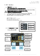
① ON ボタン
ON button
③ Lo ボタン
Lo button
② OFF ボタン
OFF button
③ Hi ボタン
Hi button
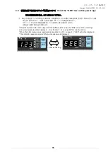
⑫ 能力レベル
Capacity level
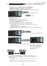
⑨ 差圧設定
Differential Pressure set
⑤ 設定値変更ボタン
Set value change button
④ 表示切替ボタン
Display button
⑩ 異 常
Warning
⑪ 運転圧力表示
Operating
Pressure
Indication(kPa)
⑧ 差 圧
Differential Pressure
⑦ 外部圧力
External Pressure
⑥ 吸込圧力
Suction Pressure
⑥
⑦
⑧
⑫
⑪
⑩
⑨
⑤
④