チコーエアーテック株式会社
Copyright CHIKO AIRTEC CO., LTD. 2013
26
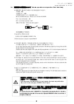
8.2 CKU-060AT2-ACC(-T,-CE)
MODEL
Страница 1: ...ies is an energy saving type clean box that realizes air technology in a compact body Please read this instruction manual thoroughly and handle this Laser Clean Series machine correctly so that you ca...
Страница 2: ...osene paint etc Explosive dust Aluminum magnesium titanium zinc epoxy etc Dust containing sparks Dust containing sparks generated by high speed cutters grinders welding machines etc Fire sources Cigar...
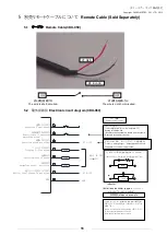
Страница 3: ...initial pressure registration 14 4 8 E EE About the E EE low suction power sign 15 5 Remote Cable Sold Separately 16 5 1 Remote Cable CKU 050 16 5 2 Electrical circuit diagram CKU 060 16 5 3 Color and...
Страница 4: ...aned factory Do not install it outdoors 0 40 80 Install the product in a place without dew condensation at room temperature ambient temperature 0 to 40 C humidity 80 or less High temperature and dew c...
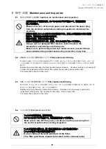
Страница 5: ...5 Repair disassembly and modification Do not disassemble or modify the machine Disassembly and modification may cause an electrical shock and injury Contact your dealer for internal inspection and re...
Страница 6: ...t securely with its dent facing downward Make sure to confirm pin positions Exhaust port MAIN POWER switch ON OFF ON OFF switch CKU 050 ACC Selector switch Power cable The cable is different in each r...
Страница 7: ...detachable CKU 060AT2 ACC Tertiary high efficiency filter 1 Primary filter Secondary Active carbon filter Differential pressure sensing gauge Consolidated jig AT2 AT2 Panel operation panel MAIN POWER...
Страница 8: ...lter are collected prevent invasion of the active carbon particle into the blower 3 3 Desorption flange If the flange diameter needs to be changed to match usage conditions the installed flange can be...
Страница 9: ...AT2 panel only 060AT Operating the product with a different power supply may cause a failure Never adopt star burst connection that may cause voltage drop If voltage drop occurs longer time is require...
Страница 10: ...Setting Change mode changes the threshold value in 5 phases of 30 to 70 at will 2 3 Suction Pressure lamp Blue 1 2 3 Detects pressure near the internal fan suction port of the dust collector and indic...
Страница 11: ...e connector sold separately MT 173 8 4 4 Confirmation before operation Confirm that the product is installed properly without any abnormality such as backlash Confirm that grounding is done correctly...
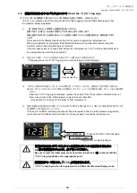
Страница 12: ...e electrical outlet Set the suction hose hood to a proper position Turn ON the MAIN POWER switch and confirm that the power indicator lamp lights Starts the dust collector AT ON Press the ON switch to...
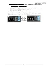
Страница 13: ...d the lamp will light If clogging occurs the C CC clog sign and current pressure will be displayed C CC 1 2 3 19 6 4 When the C CC clog sign is displayed replace the primary filter If the pressure ind...
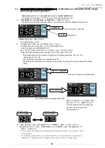
Страница 14: ...ollowing sequence 50 40 30 Initial pressure 70 60 The registered initial pressure is displayed after 30 Decreasing the value delays the clog sign display timing Increasing the value advances the displ...
Страница 15: ...is large and the airflow volume is low the E EE low suction power sign and current pressure will be displayed See Section 7 on page 22 for corrective action When the initial pressure was registered a...
Страница 16: ...rcuit diagram CKU 060 Inductor Install a noise limiter approx 33 0 1 F or diode if a relay is added Remote operation switch ON Shifting to remote mode Remote control is possible in the ON and the pane...
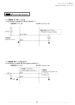
Страница 17: ...Copyright CHIKO AIRTEC CO LTD 2013 17 Connection Example...
Страница 18: ...Copyright CHIKO AIRTEC CO LTD 2013 18...
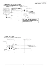
Страница 19: ...ort circuiting pins and short circuit pin to start operation Red white Remote control operation switching signal Short circuits the wires 4 and 8 to start remote operation The AT panel is disabled whi...
Страница 20: ...ng the buttons on the main unit when switching to remote operation check that pin is not shorted circuited then press and hold the ON button on the AT panel of the main unit and press the Lo or Hi but...
Страница 21: ...the primary filter replace the secondary active carbon filter The tertiary filter is able to do the same 6 4 Replacement of filter Make sure to turn off the main power and disconnect the power plug f...
Страница 22: ...get the top cover off Take out the primary filter case and replace the primary filter 2 snap locks Get the top cover off and take out the primary filter Get the top cover off and take out the primary...
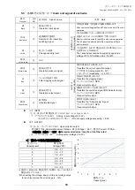
Страница 23: ...V 3A CKU 060AT ACC CE 220 240V 3A 6 6 Daily inspection When the fuse is blown out by excessive current generated by a trouble in the internal equipment replace it Inspection item Frequency Description...
Страница 24: ...ion 30 minutes later Fuses are blown out Replace fuses Refer to Fuse The suction force is deteriorated Filters are clogged Replace filters Clogged filters lead to the failures 3 and 4 below Particles...
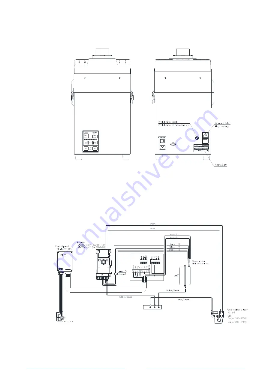
Страница 25: ...Copyright CHIKO AIRTEC CO LTD 2013 25 DC BL PT TORANCE 8 Indication of DANGER Labels Electrical Circuit Diagram 8 1 CKU 050 ACC TW MODEL CKU 050 ACC CKU 050 ACC TW...
Страница 26: ...Copyright CHIKO AIRTEC CO LTD 2013 26 8 2 CKU 060AT2 ACC T CE MODEL...
Страница 27: ...60 2 4 1 8 58 68 22 CKU 060AT ACC CE 150 220 240V 1 7 50 60 2 4 1 8 58 68 22 A B Note The Noise column indicates a value dB on the scale A at 1 m on the main body side when hose is connected to the su...
Страница 28: ...bject to change without prior notice Memo about purchase Model Manufacturer s serial number Date of purchase Start of operation Your name Address Phone Person in charge LTD 562 0012 2 27 24 2 27 24 Ha...