


チコーエアーテック株式会社
Copyright CHIKO AIRTEC CO., LTD. 2013
21
6
保守・点検
Maintenance and Inspection
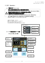
6.1
保守点検時の注意事項
Cautions on maintenance and inspection
6.2
060AT
フィルタの交換時期について
Filter replacement timing
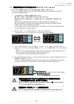
目詰まりした場合、「C
.
CC」の目詰まりお知らせサインが点灯しましたら、1次フィルタを交換してください。また、1次フ
ィルタを交換しても、目詰まりサインが消えないときには、2次(活性炭)フィルタを交換してください。3次フィルタも同
様です。
Replace the primary filter when the filter saturation lamp is turned on. But when the lamp is not turned off
in spite of the replacement of the primary filter, replace the secondary (active carbon) filter.
The tertiary filter is able to do the same.
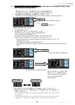
6.3
050
フィルタの交換時期について
Filter replacement timing
吸引力が低下したら、1次フィルタを交換してください。また、1次フィルタを交換しても解消されない場合は、2次(活
性炭)フィルタを交換してください。3次フィルタも同様です。
Replace the primary filter when suction force declines.
But when it is not improved in spite of the
replacement of the primary
filter, replace the secondary (active carbon) filter.
The tertiary filter is able to do the same.
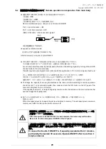
6.4
フィルタの交換
Replacement of filter
点検時は必ず電源を切り、コンセントからプラグを抜いて、電路遮断を
行ってください。
Make sure to turn off the main power, and disconnect the power plug
from the electrical outlet before starting inspection to shut down the
electricity.
摩耗や破損したフィルタをそのまま使用すると、吸込んだ粉塵を大気に再飛
散させ、電気部品の損傷となります。
機械の故障、事故を未然に防ぎ、
末永くご使用頂けますよう、点検、手入れは必ず行ってください。
Using a worn or damaged filter releases sucked dusts to the
atmosphere, and damage electrical parts.
Make sure to perform inspection and maintenance to prevent failures
and accidents in the product and use the product for a long time.
フィルタの交換時は、電源を切り、
コンセントからプラグを抜いて、電路遮断を行ってください。
Make sure to turn OFF the power, and disconnect the power plug from
the electrical outlet before starting inspection.
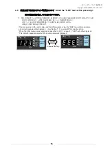
フィルタ取り付の際には、裏・表を間違えないようご注意ください
(フィルタ格子の枠が排気面側です)
Do not confuse the back and front of the filter.
(The filter grid frame should be located on the exhaust side.)