


チコーエアーテック株式会社
Copyright CHIKO AIRTEC CO., LTD. 2013
10
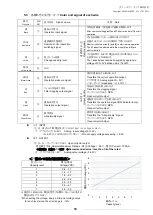
名称
Button name
ランプ色
Lamp color
説明
Description
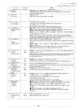
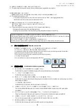
①
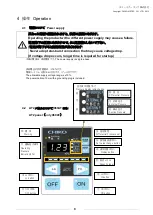
ON
ボタン
ON button
―
運転を開始します。
(
同時にボタン左上の緑ランプが点灯します
)
Press this button to start equipment operation.(The green lamp at the upper left
corner of the button lights.)
②
OFF
ボタン
OFF button
―
運転を停止します。
Press this button to stop equipment operation.
③
Hi
/
Lo
ボタン
Hi/Lo buttons
―
Lo
:
1
回押すごとに1レベル降下
Lo: Each press of this button decreases the setting by 1 level.
Hi
:
1
回押すごとに
1
レベル上昇
Hi: Each press of this button increases the setting by 1 level.
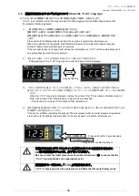
④
表示切替ボタン
Display Selector
button
―
■:
1
回押すごとに差圧・外部圧力・吸込圧力の順番に切り替わます。
■:
Each press of this button changes the displayed indication in the sequence of
Differential Pressure, External Pressure and Suction Pressure.
■:通常モード中に
2
秒間押すと、初期の圧力を登録し、再度、長押し
2
秒間で初期登録し
た圧力の値をリセットします。※
1
■:
When this button is pressed and held for 2 seconds while the equipment is in
normal mode, initial pressure is registered. When it is pressed again and held for 2
seconds, the registered initial pressure value will be reset.*1
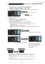
⑤
設定値変更ボタ
ン
Setting
Change button
―
長押し
2
秒間でフィルタ目詰まり設定値変更モードに移行します。
Press and hold this button for 2 seconds to activate the filter clogging setting change
mode.
■:設定値変更モード中に、
1
回押すごとに目詰まり閾値を
30
~
70
の
5
段階、任意に変更
できます。※
2
※
3
■:
Each press of this button while the equipment is in Setting Change mode
changes the threshold value in 5 phases of 30 to 70 at will.*2*3
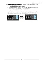
⑥
吸込圧力ランプ
Suction
Pressure lamp
青
Blue
集塵機内ファン吸込み口付近での圧力を検知し、
1
、
2
、
3
次フィルタと外部圧力を加算した
合計の圧力を示しています。
Detects pressure near the internal fan suction port of the dust collector, and indicates
the total pressure level including primary/secondary/ tertiary filter pressure and
external pressure level.
⑦
外部圧力ランプ
External
Pressure lamp
青
Blue
集塵機吸込み口から吸込みフードまでの圧力を示します。
Indicates the pressure in the section between the suction port and suction hood.
⑧
差圧ランプ
Differential
Pressure lamp
青
Blue
1
、
2
次フィルタの前後で検知した圧力の差を示しています。
Indicates the pressure difference between the area in front of the primary/ secondary
filter and the area behind it.
⑨
差圧設定ランプ
Differential
Pressure Setting
lamp
黄
Yellow
設定値変更モード中にランプが点灯します。
This lamp lights when the equipment is in Setting Change mode.
⑩
異常ランプ
Warning
lamp
赤
Red
異常温度又は、インバーターに(過負荷など)異常が発生した場合、点灯します。
→対策方法は
22
ページ
7.
⑥項を参照ください。
This lamp lights when a temperature error or inverter error
(such as an overload) occurs.
→
For corrective action, refer to Section 7.
⑥
on page 22.
⑪
運転圧力表示
Operating
Pressure
indication
―
■:現状圧力を
3
ケタで表示しています。(
3
ケタ表示:
0~9.99KPa
)
■:
Indicates the current pressure with 3 digits.(3-digit indication: 0 to 9.99kPa)
■:フィルタが目詰まりした場合、「C
.
CC」と現状圧力を繰り返し表示します。
■:
Displays “C.CC” and current pressure alternately when the filter becomes
clogged.
■:吸引力低下した場合、「
E.EE
」と現状圧力を繰り返し表示します。
■:
Displays “E.EE” and current pressure alternately when suction pressure
decreases.
⑫
能力レベルランプ
Capacity Level
lamp
緑
Green
能力レベルを表示します。
(
レベル
1
~
7)
Indicates capacity level.(Levels:1 to 7)