


チコーエアーテック株式会社
Copyright CHIKO AIRTEC CO., LTD. 2009
7
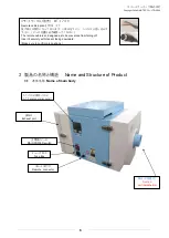
3.2
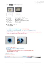
標準付属品
Standard accessories
1次フィルタ
:粉塵やヒュームを収集・吸着します。
Primary filter
:
Collecting /Adsorbing fine dust and fumes.
2次フィルタ
:電気部品を粉塵から守ります。
Secondary filter
:
Protecting the circuit and the
electrical parts.
排気フィルタ
:排気をクリーンにします。
Exhaust
filter
:
Exhaust treatment
本体差込電源コード(
3
m)
×1
Power
cable(
3m)
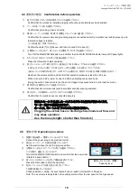
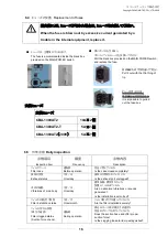
3.3
脱着フランジ
Desorption flange
Detachable flange
ご使用の環境に応じて吸込み口径の変更が必要な場合、工具なしでフランジを交換することができます。
(交換用フランジ別売)
If th flange diameter needs to be changed to match usage conditions,the installed flange can be changed without
having to use any tools.(Replacement flanges are sold separately.)
<取り外し方>
<Removal method>
右に回すと閉まり、左に回すとフランジを取り外すことができます。
出荷時装着径φ
75
Turn the flange counterclockwise to remove it. Turning it to clockwise tightens the flange.
Diameter of installed flange: 75 mm
<交換可能なフランジ径>
<Replacement flange diameters>
型 式
model
フランジ径
Flange diameter
CBA-1300AT2
φ
75
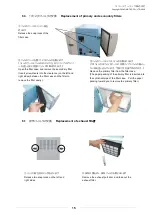
1次フィルタ
Primary filter
2次フィルタ
Secondary filter


