


チコーエアーテック株式会社
Copyright CHIKO AIRTEC CO., LTD. 2009
10
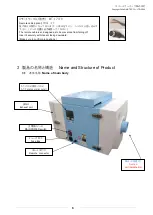
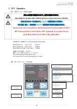
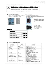
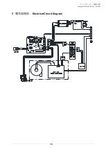
能力レベルスイッチ(7段階)
Capacity level
4.4
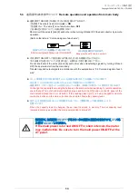
運転前の確認
Confirmation before operation
①
据え付け状態にがたつき等の異常がないかを確認してください。
Confirm that the product is installed properly without any abnormality such as backlash.
②
アースはとれているかを確認してください。
Confirm that grounding is done correctly.
③
電源コ-ド、ア-スの接続、絶縁、定格電圧になっているかを確認してください。
Confirm that the power cable and grounding plug are connected correctly, insulation is provided properly, and
the rated voltage is realized.
①~③を確認し、用意できましたら、
Confirm the items [1] to [3] above, and then proceed to the item [4].
④
主電源スイッチを入れて、
AT
パネルの主電源ランプの点灯を確認してください。
Turn ON the MAIN POWER switch, and confirm that the MAIN POWER indicator lamp of AT-panel lights.
⑤
AT-
パネルの
ON
スイッチを押して運転を確認して下さい。
Press the ON switch to start operation.
⑥
能力レベルスイッチで、最大能力にし、運転圧力が
4.0
k
Pa
以下であることを確認してください。
4.0
k
Pa
以上になった場合には、吸込みホース等を調整し、
4.0
k
Pa
以下にしてください。
(吸込みホースが細すぎる場合や、ふさがれている場合には、負荷がかかり過ぎ、故障の原因となります。)
Maximize the volume switch, and confirm that operation pressure is less than 4.0 k pa.
When it is over 4.0 kPa, lower it under 4.0 kPa by adjusting the suction hose.
(Using the suction hose which is too thin and is clogged may cause failure by the load too much.)
⑦
異常音が
(
金属音など
)
ないか確認してください。
Confirm that abnormal sounds (such as metallic sounds) are not generated.
⑧
吸込みホ-スの接続がしっかりつながれているか確認してください。
Confirm that the suction hose is connected securely.
4.5
運転手順
Operation procedure
①
設置状態を確認し、電源コンセントを入れてください。
Connect the power plug to the electrical outlet.
②
吸込みホース(フード)を適切な位置にセットします。
Set the suction hose (hood) to a proper position.
③
主電源スイッチを入れて、ランプの点灯を確認してください。
(この状態で、運転モードに入ります)
Turn ON the MAIN POWER switch, and confirm that the power indicator lamp lights.
(
Starts the dust collector
)
④
AT-
パネルの
ON
スイッチを押して運転を確認して下さい。
Press the ON switch to start the operation.
⑤
能力レベルスイッチで任意の能力に設定して下さい。
7
段階の調整となっております。
Choose operation
ability
in seven levels. Push Lo-switch or Hi-switch in AT-panel.
Note: The air volume is adjustable in the nonstop method from the low speed to the high speed.
吸込みホースや吐出しホースがふさがれると空気が流れなくなり、
モーター焼けの原因となります。
ホースは、5メートル以下のものをご使用ください。
Clogging the suction hose or discharge hose hinders air flow, and
may stops operation.
Use the hose (length: shorter than 5 meters)


