background image

31

 VEHICLE GRAPHICS

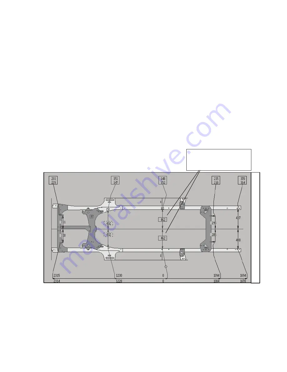
Vehicle Graphics are top view drawings of a vehicle’s structural components. In the Laser Lock program, they appear on all Laser Lock 

Windows. Vehicle Graphics match make, model, and year of vehicle identified in Vehicle Information Dialog Box. Although each Graph-

ic shows general shape and location of reference points, program’s Zoom feature allows operator a closer, more detailed look.

Laser Lock measurements are displayed on Vehicle Graphics. (See Figures 37 and 38.)

Datum Height Measurements appear in boxes across top of Vehicle Graphic with top numbers representing right side of vehicle and 

bottom numbers representing left side.

Centerline Width Measurements appear directly on Vehicle Graphic with numbers above centerline representing right side of vehicle 

and numbers below centerline representing left side.

Datum Length Measurements appear along horizontal line at bottom of Vehicle Graphic with numbers above the line representing right 

side of vehicle and numbers below the line representing left side. Datum length measurements originate at the Body Zero Line/Plane 

which can be established at front or rear of vehicle’s center section. This line/plane is identified by its width measurements that appear 

inside a solid box.

NOTE:

 Indicator lines link reference points on Vehicle Graphic to their respective measurements.

  Figure 

37

Body Zero Line/Plane width 

measurements appear inside 

solid box


Height

Length

R

L

R

L

R

L

Содержание LASER LOCK

Страница 1: ...USERS MANUAL For Spanish See DVD sent with unit French German etc 788438 2014 Chief Automotive Technologies CO8839 Rev 1 22 14 LASER LOCK LIVE MAPPING SYSTEM ...

Страница 2: ...WS 7 Workstation 7 Body Scanner and Tray 8 Targets 9 Target Base 10 Attachments Clips Extensions 11 Magnetic Attachments 11 Bolt Attachments 12 Hole Attachments 12 Extensions 13 Upper Body Bar Assembly 14 Spacers and 3 Inch Bolts 16 Chief Specifications Data 16 Literature 16 Diskettes and CDs 17 COMPONENT MAINTENANCE 18 COMPONENT TROUBLESHOOTING 20 III LASER LOCK PROGRAM 21 STARTING UP LASER LOCK ...

Страница 3: ...ir or replacement of components which are defective and which have not been misused care lessly handled or defaced by the repair or repairs made or attempted by others The buyer agrees that no other remedy including but not limited to incidental or consequential damages for lost profits lost sales injury to person or property or any other incidental or consequential loss shall be available to him ...

Страница 4: ...e com puter which performs the triangulation and Target identification functions About This Manual This manual provides information on basic hardware components It also provides pertinent informa tion regarding startup shutdown procedures examples of on screen Windows Dialog Boxes and Vehicle Graphics Keyboard Mouse Pen functions Special Keys and information on how to use the Laser Lock Help Text ...

Страница 5: ...gth width height is considered normal according to Chief Automotive Technologies experience In Arrow Display Mode reference point measurements that exceed toler ance appear in red whereas those falling within tolerance appear in blue Some reference points used for dimensioning the same make and model of vehicle vary from one manufacturing plant to another Also periodic manufacturing improvements c...

Страница 6: ...result from welder use and it may cause the computer to fail Also avoid metal to metal con tact between all components i e Workstation Body Scanner Welder Vehicle Platform Controls On Off switch on Workstation Allows power to Computer and other electrical components On Off switch on Body Scanner Allows power to Body Scanner including lasers Laser Safety Information Laser Power Output 2 5 mw 4 2 x ...

Страница 7: ...Vehicle Service Group 2010 All Rights Reserved No part of this work covered by copyrights hereon may be reproduced or copied in any form or by any means including but not limited to graphics electronic or mechanical including photocopying taping printing or information storage and retrieval systems without written permission of Vehicle Service Group Madison Indiana U S A All inqui ries relating to...

Страница 8: ...side U S A contact an authorized Chief Automotive Technologies representative Computer Program Updates Updates and changes to computer programs will be issued from time to time via computer DVDs Explanations of changes and instruc tions for installing them will accompany the DVDs Specification Updates Corrections Annually and as required updates and additions to vehicle specifications and instruct...

Страница 9: ...Clips 7 Display Monitor 1 Upper Body Bar Keyboard Anchoring Spacer Printer Literature Workstation 3 Not shown in Figure 1 see following Power Supply pages Body Scanner 4 and Tray 5 Figure 1 Use of controls adjustments or performance of procedures other than those specified in this manual may result in a breach of warranty and could result in hazardous radiation exposure See CAUTIONS on Workstation...

Страница 10: ... Laser Lock to a 110 volt 15 amp power source or 220 volt 5 amp power source Check voltage requirements for Laser Lock system being used A single purpose line is recommended Do not use circuits subject to frequent interruptions or outages Avoid circuits with power surges such as from welders and some power tools Built in surge protector may not be sufficient to protect against current fluctuations...

Страница 11: ...arrow Figure 4 Body Scanner on off switch is shown in Figure 5 Inset photo for Figure 3 shows connections for a 220 volt 5 amp Laser Lock System Computer and Body Scanner are precision electronic tools Movement of components must be done with care Do not move Workstation during a continuous measurement or during program accessing IMPORTANT 110 Volt System Power Cable Power Cable Body Scanner Cable...

Страница 12: ...y see Figure 7 Cable port must be under left side driver s side of vehicle This positioning allows Body Scanner to be synchronized with computer program Body Scanner does not need to be square to vehicle or level Make sure however it remains in Tray and Tray is stable It is permissible to reposition Tray any time or shift Body Scanner in the Tray Laser Lock recalibrates any repositioning in its ne...

Страница 13: ...ust be installed on the Lower Bar of the Upper Body Bar Assembly directly below their respective Pointers Target Number 45 must be in the center of the Lower Bar Figure 8 Figure 9 Target Base Any Target except Targets numbered 43 44 and 45 can be used with the Target Base See Figure 9 Target Base sits on platform and Target is projected upward from it to a reference point When using Target Base to...

Страница 14: ... in attachment s clip The magnet on the attachment is strong and will maintain its holding power if cared for properly A Magnet Keeper see Inset Figure 11 should be positioned on magnet when the attachment is not in use Never use arc welder or heat near Magnetic Attachment as this tends to reduce its holding power IMPORTANT Figure 10 Figure 11 Bolt Attachments Bolt attachments work equally well on...

Страница 15: ...se until operator inputs correct information in Change Attachment Dialog Box IMPORTANT Figure 12 Figure 13 Figure 14 Hole Attachments Magnetic Hole Attachments snap into all types of reference holes They work equally well on the bottom of a structural component or on the side of a structural component The attachments feature a nylon base which swivels to allow for easy Target adjustments Magnetic ...

Страница 16: ...nt Laser Lock program however assumes Magnetic Snap In or small Metal Clip Attachments are in use until operator inputs correct information in Change Attachment Dialog Box IMPORTANT Figure 15 Figure 16 Figure 17 Extensions Target Extensions are available in lengths of 156mm and 256mm See Figure 18 A third extension is C shaped for reaching around ob structions The Extensions allow greater flexibil...

Страница 17: ...ths of 102mm 178mm and 432mm Three Targets Nos 43 44 45 mounted to Lower Bar measure height width centerline and length of strut tower or other upper body reference points In addition to components listed Bolt Hole Caps and Stud Hole Caps ranging from 5 to 17mm in diameter allow the assembly to be mounted to open bolt holes or studs See Figures 22 and 23 The config uration of the cap positions the...

Страница 18: ...sing Next install Lower Bar with three Targets installed and remaining Vertical Scale If needed adjust height of Lower Bar to enable Body Scanner to view all three Targets IMPORTANT 1 Target Number 45 must be in center of Lower Bar and Target Numbers 43 and 44 must be under their respective Pointers See Figure 26 2 Body Scanner s Lasers should strike near center of Target faces 3 Length of Vertica...

Страница 19: ...ing Targets to hang vertically Spacers and 3 inch bolts are provided for offsetting clamp bar Chief Specifications Data Specifications of domestic and foreign vehicles are stored in the Laser Lock Computer along with provisions for periodic updates Literature Literature provided with Laser Lock system includes Laser Lock Users Manual Laser Lock Parts Manual and user manual s for Com puter Microsof...

Страница 20: ...t label and slide it from drive slot Figure 27 Update DVDs The Computer provided with the Laser Lock system comes fully loaded with operational software Vehicle Graphics and vehicle spec ifications Periodic updates to these are made available as needed Updates are sent in DVD format To make updates refer to proce dures identified in Help Text and any special instructions mailed with the update DVD...

Страница 21: ... water and a mild detergent Shake off excess water allow to dry and reinstall Body Scanner Care Do not plug or unplug cable from Body Scanner unless it is turned off Keep Body Scanner away from areas being undercoated primed or painted Keep heat away from Body Scanner when using a torch for thermal stress relieving of structural components Clean all Body Scanner parts with a lint free low abrasion...

Страница 22: ...n cloth and a good quality glass or ammonia cleaner Do not use solvents or alcohol based cleaners on Monitor screen or other computer parts Be sure system s pow er is off while cleaning is performed Do not remove the clear plastic skin covering Keyboard Wipe it clean with a soft cloth See Figure 28 Lint free low abrasion cloth Figure 28 ...

Страница 23: ... not functioning In addition to information listed here and in the Laser Lock Help Text refer also to User s Manuals for the Computer and Printer If troubleshooting problem s can not be solved after reviewing these sources of information contact Chief Automotive Technologies for assistance See Page 4 for instructions No Power To System Components Computer Monitor Keyboard Mouse Body Scanner Printe...

Страница 24: ...start after turning on the cabinet switch the push the power button on your computer Computer will examine its circuits and prepare to run the Laser Lock system This process is called booting up the computer It takes several seconds to complete When the Laser Lock Title Screen opening window is displayed see Figure 30 the booting up procedure is complete 110 Volt System 220 Volt System Figure 29 F...

Страница 25: ... allows the operator to select the desired vehicle from a list of vehicles that have not yet been finished When selecting Recall Saved Measurement a Dialog Box allows the operator to search for the vehicle by customer name vehicle description or work order number PREFERENCES The Laser Lock Title Screen also allows operators to access the system s Preferences Dialog Box See Figure 31 Tabs within th...

Страница 26: ...lection method See Tool Bar Icons Buttons in Laser Lock Help Text The selection of menu items or tool bar items often prompt the appearance of Dialog Boxes on Screen Dialog Boxes allow operators to supply additional information to complete a task Some Dialog Boxes require a selection from a list of options whereas others require the inputting typing of information See explanation of Dialog Boxes a...

Страница 27: ...Lock on line Help Text Title Bar Identifies Window Located across top of Window Menu Bar Identifies Menu Headings Located across top of page below Title Bar Menu Headings Identifies menu lists that are available Menu List Identifies tasks computer is ready to perform Scroll Bars Used to expand Window when enlarged image of Vehicle Graphic exceeds display area Tool Bar Icons Buttons Used to perform...

Страница 28: ... Specifications Mode Wizard On Off Button Edit Change Attachment Delete Base Target Delete All Base Targets Mechanics Measure Cancel Display Help Title Bar Laser Lock Live Initial Inspection Base Reference Entry Chevrolet Cavalier Menu Headings Point Information Dialog Box Scanner View Dialog Box ...

Страница 29: ...ext Title Bar Identifies Dialog Box Located across top of Dialog Box Command Button Used to perform certain functions quickly Graphic suggests purpose or identity of function Field Specific line for inputting viewing editing information Cursor Operator controlled indicator that appears on Windows Dialog Boxes and Help Pages Changes shape as per application List Box Listing of choices that are avai...

Страница 30: ...lose Buttons Title Bar Cone Target Number Error Message Camera Icon photos available Radio Button Indicator Close Button Field Command Buttons Customer Vehicle Work Order Information Sections Customer Vehicle Work Order Tree Down Arrow accesses List Box with scroll bars DIALOG BOX EXAMPLES Figure 34 Figure 35 Figure 37 ...

Страница 31: ...bers representing left side Centerline Width Measurements appear directly on Vehicle Graphic with numbers above centerline representing right side of vehicle and numbers below centerline representing left side Datum Length Measurements appear along horizontal line at bottom of Vehicle Graphic with numbers above the line representing right side of vehicle and numbers below the line representing lef...

Страница 32: ...e Actual Measurements mode shows only current measurements taken by Laser Lock See Figure 38 previous page When specifica tions don t exist in the Laser Lock data base this mode can be used to repair structure through comparison measurements Specifications mode shows only a vehicle s published specifications as obtained from the Laser Lock Data Base It is for reference purposes only Target Graphic...

Страница 33: ... combination Press and hold down one of the Alt Keys and then press underlined letter in heading For example Combination Alt F accesses File heading To select a menu item below heading press only underlined letter of the item s name Then press Enter Key NOTE Menu items below headings can also be selected using Arrow Keys and Enter Key Vehicle Graphic To move Cursor around Vehicle Graphic when ente...

Страница 34: ...s to select Close and press Enter Key again 3 When two Dialog Boxes are displayed at same time only one will be activated To activate the other press Alt F6 Key Title Bar of activated Dialog Box will appear highlighted To Access Laser Lock Help Pages 1 To access Help Index press F1 Key upon accessing a Laser Lock Window or select Index from list of items under Help heading in any Menu Bar 2 To acc...

Страница 35: ...ct non active Dialog Box by positioning cursor on that box and pressing and releasing clicking Title Bar of activated Dialog Box will appear highlighted To Access Laser Lock Help Pages 1 To access Help Index select Index from list of items under Help heading or select Help icon in Tool Bar at right side of screen 2 To access Help page that relates to a specific Dialog Box select Help icon which ap...

Страница 36: ...nus close Dialog Boxes access other Dialog Boxes enter Targets on Vehicle Graphic select Command Buttons dispose of Help Pop ups Serves same function as Mouse button Escape Key Used in Keyboard operation only Used to back up within Menus and serves same function as X Cancel Command Button on Dialog Boxes Function Keys Keys marked F1 F2 F5 and F6 are Special Keys that perform special functions F1 F...

Страница 37: ... terms or phrases See Example Figure 41 The Laser Lock Help Text can be accessed in a variety of ways and is available any time the system is up and running Operators have flexibility of jumping to specific Help Pages or Pop Ups or they can access Index Pages if needing to search for a topic The following information outlines various ways to access Help Text For information on using Help Pages ref...

Страница 38: ...ns The lone exception i_s when Title Bar of Window indicates Base Reference Entry The F1 Key then accesses Base Reference Entry procedures From this procedures page operator has option to access definitions for Base Reference Entry Menus and Tool Bar Icons NOTE 1 Dialog Boxes are active when Title Bars are highlighted 2 When an active Dialog Box appears remove it from Window prior to pressing F1 K...

Страница 39: ...ing desired key word or phrase or Icon press Enter Key If using the Mouse position Cursor on Key word or phrase or Icon Cursor changes to shape of hand when correctly positioned See Figure 44 Then select word or phrase or Icon by pressing and releasing clicking left side button on Mouse Help Pages and Pop Ups often feature illustrations and or photos which help clarify procedures or identify the L...

Страница 40: ...s allow only limited sizing of Help Page Using the Mouse position Cursor at vertical or horizontal border or at corner of Help Page Cursor will change to shape of double arrow Press and hold down left side button on Mouse Drag Cursor to enlarge or reduce Help Page and then release Using Keyboard press Alt Space Bar to access menu list below Control Menu Symbol at left side of Title Bar Using Arrow...

Страница 41: ...f common terms used in Windows Program Selec tion of a term from listing accesses its definition To access on line How To Use Help System first access a Laser Lock Help Page and do one of the following Select How To Use Help from list of items under Help heading or press F1 Key Control Menu Symbol List of items under Control Menu Symbol see Figure 48 allows operator to restore Help Page to normal ...

Страница 42: ... and from Start Menu List click Laser Lock Electronic Measuring and select Laser Lock Tutorial Many of the videos contained in the Tutorial are also accessible from related Help Text pages Clicking the Camera Icon see Figure 47 on these pages accesses the video Figure 47 Laser Lock HELP WIZARD The Laser Lock Help Wizard available on newer operating systems is an on screen guide that assists the te...

Страница 43: ...43 Notes ...

Страница 44: ...966 Industrial Dr Madison IN 47250 Phone 800 445 9262 Fax 866 275 0173 www chiefautomotive com Chief reserves the right to alter product specifications and or package components without notice ...

Отзывы: