


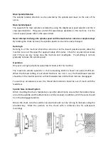


Note:
For the correct locking condition, each cam must be tightened with the index line between
the two “V” marks on the nose.
Do not interchange chucks or other attachments without first check each cam for the correct
locking position.
To adjust the camlock studs, remove the lock screw B and turn the stud one full turn in or out
as required. Refit and re-tighten the screw B. A datum ring on the camlock stud has been
machined into the stud as a guide to the setting for the camlock studs.
11. Thread and Feed Selection
All threads and feeds are indicated on the table fitted to the top and front of the gearbox and
are selected by using the feed selector handles on the feed box.
Manual Operation
The carriage is moved by using the handwheel located on the apron, the cross slide is moved
by using the handwheel on the saddle and the compound rest is moved by turning the small
handwheel. The slides can all be anchored by turning the lock bolts on the top of the slide.
Automatic Feed Operation
Engage the feed/thread lever to the feed icon and use the feed selector levers to engage the
feed speeds to start the feed rod. If the feed lever on the apron is then used, pushing the
lever upwards will engage the cross feed, downwards engages the longitudinal feed.
Thread Cutting Operation
The direction of thread cutting is controlled by the feed direction lever and the cutting rate
selected by the feed handles, move the feed/thread lever to the thread cutting icon to engage
the leadscrew. Operate the thread cutting engagement lever (push down) to engage the half
nut with the leadscrew.
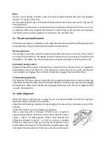
12. Lathe Alignment
When the lathe is installed and is ready for use, it is recommended to check the machines
alignment before putting it into operation.
Alignment and levelling should be checked regularly to ensure the continued accuracy of the
machine.
Check the machine as per the following procedure:
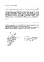
Take a steel bar with a diameter of 50mm and a length of
approximately 200mm and lock it in the chuck without using a
centre. Take a cut along approx. 150mm and measure the
difference between A and B. In order to correct a possible
difference, loosen the screw (j) clamping the headstock to the
bed and adjust the position of the headstock using the set screws
and repeat this procedure until the measurements are the same.
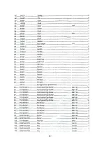
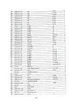
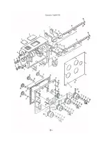
Содержание Coventry Pro
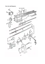
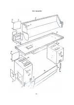
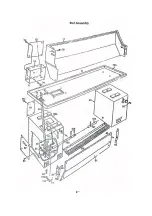
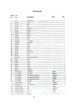
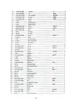
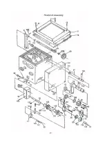
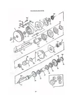
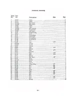
Страница 16: ...Parts List and Diagrams...
Страница 17: ......
Страница 18: ......
Страница 19: ......
Страница 20: ......
Страница 21: ......
Страница 22: ......
Страница 23: ......
Страница 24: ......
Страница 25: ......
Страница 26: ......
Страница 27: ......
Страница 28: ......
Страница 29: ......
Страница 30: ......
Страница 31: ......
Страница 32: ......
Страница 33: ......
Страница 34: ......
Страница 35: ......
Страница 36: ......
Страница 37: ......
Страница 38: ......
Страница 39: ......
Страница 40: ......
Страница 41: ......
Страница 42: ......
Страница 43: ......
Страница 44: ......
Страница 45: ......
Страница 46: ......
Страница 47: ......
Страница 48: ......
Страница 49: ......


