Chemtrac HydroAct HA4 Скачать руководство пользователя страница 56

56

Chapter 3. Sensors

3.1.4.17

Parameter Flags

The parameter flags show the state of an individual parameter of a particular sensor. These flags can

either be active or not. To see the state of these parameter flags, select:

Options

Device Flags

Parameter Name

Flags that are active are shown in black text on a white background, those that are not active are

grayed out. Available flags are:

Alarm 1 active

The first parameter data alarm is active and triggered.

Alarm 2 active

The second parameter data alarm is active and triggered.

Averaging enabled

The value displayed for this parameter is averaged.

Threshold 1 active

The first parameter threshold is active and triggered.

Threshold 2 active

The second parameter threshold is active and triggered.

3.1.4.18

Alarms and Thresholds

Alarms are the means by which values obtained from sensors cause visible, audible or physical actions

to occur. Alarms are not to be confused with relays. An alarm in a HydroAct 4 unit will create a visible
bar across the top of the screen and sound a buzzer. One flow alarm per sensor and two data alarms
per parameter are available.

Thresholds are similar to alarms except that they are events that are supposed to occur and

therefore will not cause the instrument to go into “Alarm”. Thresholds are most frequently used to
trigger relays to cause something to happen when a parameter reaches a value.

To access the alarm and threshold configuration select:

Options

Alarms & Thresholds

Parameter Name

The display has a tab for each alarm and threshold. Navigate to the tab using the right and left

buttons indicated on the bottom of the display or navigate through the settings using the up and down
arrows. Options are:

Enabled

Selecting this option turns the alarm/threshold on or off.

Set

The

Value

is used to trigger the alarm or threshold

7

. The

Delay

is the amount of time the value

has to exceed the set value before the alarm/threshold is triggered.

Reset

The

Value

is used to clear the alarm or threshold. The

Delay

is the amount of time the value

has to exceed the reset value before the alarm/threshold is cleared.
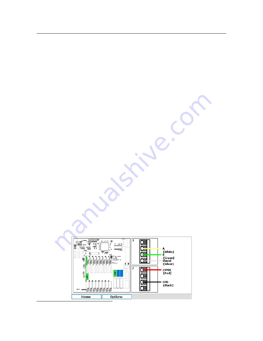
3.1.4.19

Connections

As the HydroAct 4 is a modular system the exact wiring details will be specific to each order. Electrical

connections required can be viewed by selecting:

Options

Connections

7

A set value above a reset value will result in a rising alarm. A set value below a reset value will result in a falling alarm.

Содержание HydroAct HA4

Страница 1: ...HydroAct 4 User Manual Chemtrac Inc Firmware Version 1 19 November 15 2017...

Страница 2: ...tted in any form or by any means including photocopying recording or other electronic or mechanical methods without the prior written permission of the publisher except in the case of brief quotations...

Страница 3: ...Operation 7 I Analyzer 2 Overview 11 2 1 Safety Precautions 12 2 1 1 Installation Maintenance and Inspection 12 2 1 2 Unauthorized Modification 12 2 1 3 Impermissible Modes of Operation 12 2 1 4 Chem...

Страница 4: ...4 Operation 46 3 1 5 Maintenance 57 3 1 6 Troubleshooting 60 4 Controls 63 4 1 PID Control 63 4 1 1 General Information 63 4 1 2 Operation 65 5 Outputs 75 5 1 Analog Outputs 75 5 1 1 General Informati...

Страница 5: ...ons under the main heading Safety Precautions the special safety precautions outlined in other sections must also be observed This manual has been supplied electronically A hard copy is available on r...

Страница 6: ...ar with and have understood the contents of this manual 1 1 3 Important Safety Instructions When installing and using this electrical equipment basic safety precautions should always be ob served incl...

Страница 7: ...1 1 Safety Precautions 7 1 1 4 Safe Operation The safety instructions contained in this manual must be observed The owner is responsible for ensuring compliance with local safety regulations...

Страница 8: ......

Страница 9: ...I 2 Overview 11 2 1 Safety Precautions 2 2 Technical Data 2 3 Installation 2 4 Operation Analyzer...

Страница 10: ......

Страница 11: ...acturer is not liable for damage caused by improper or non designated use Every analyzer is carefully checked before leaving the factory If for any reason you are unhappy with your purchase please con...

Страница 12: ...ire hazard No parts are suitable for use in a hazardous rated area When working with this equipment the accident prevention regulations applicable on site must be observed and the specified personal p...

Страница 13: ...he following is a list of the factors that need to be taken into consideration This list is not intended as a check list neither is it implied that the list is complete Ensure that the mounting allows...

Страница 14: ...ounted or mounted on a handrail or pole1 The HydroAct 4 electronics should be mounted so that it is away from sources of heat or direct sunlight it is vertical there is sufficient clearance above to a...

Страница 15: ...2 3 Installation 15 HydroAct 4 Panel Mounting A HydroAct 4 front section B Four M5 bolts C HydroAct 4 rear section D Rubber gasket E Panel F Support bracket G Four M5 washers H Four M5 nuts...

Страница 16: ...ail mount kit By turning the brackets through 90 the analyzer can also be pole mounted HydroAct 4 Handrail Mount ing A HydroAct 4 B Large bracket C Four M5 8mm bolts D Handrail E Small bracket F Two M...

Страница 17: ...ress to open connectors or screw terminals An insulated screw driver can be used to operate the connector Each instrument has a large number of possible wiring combinations depending on which sensors...

Страница 18: ...Left Right and Select button it is possible to navigate to any part of the analyzer by highlighting the icon and selecting it Devices are firmware modules that control a physical device such as a sen...

Страница 19: ...ol outputs For details of how home screens are defined and configured see section 2 4 5 3 2 4 4 User Authentication When attempting to access a function that requires authentication you will be taken...

Страница 20: ...security access is enabled see section 2 4 5 4 and different security access is required press and hold the select button on the desired device tile in the main menu for a few seconds The login screen...

Страница 21: ...be set to any supported language Use the drop down list to select the language of choice Time Zone Select the required time zone The internal clock stores the time in UTC format Therefore changing the...

Страница 22: ...box is ticked then the Analyzer tile will be hidden as default on the main menu Logs tile If the checkbox is ticked then the Logs tile will be hidden as default on the main menu 2 4 5 3 Home Screens T...

Страница 23: ...elow if applicable For this example select Generic and press Create Editing an existing Generic home screen or creating a new Generic home screen will display the above form Select the desired layout...

Страница 24: ...ected window Options are Device or Data Log Data Log If Data Log is selected in the type field this option will be available Select the data log to display Device If Device is selected in the Type fie...

Страница 25: ...access to output devices such as relays and analog outputs Control Controls access to control devices such as PID Event Controls access to event devices such as timers and schedulers With each of thes...

Страница 26: ...p Information given for each Node4 includes board number board type firmware version number and unique serial number Each enclosure in a system contains a base board These boards are numbered 1 5 9 an...

Страница 27: ...refers to the micro SD card and a total size of 0 00MB indicates that the card is missing or not detected The device list shows which software modules are installed and active on the anlayser To acce...

Страница 28: ...gineer 2 4 5 9 Device Codes Device codes enable firmware modules Adding new hardware or software features usually requires adding device codes Devices codes can be entered directly using the user inte...

Страница 29: ...display the last time logs were successfully backed up With a SD card inserted in to the analyzer press the Backup button to begin Log entries since the last successful backup will be written to the...

Страница 30: ...ata Log Enter the name to identify the data log and the log interval Available options are 1 2 5 10 15 20 30 minutes or 1 hour Press Next to continue Select from a list of available parameters signal...

Страница 31: ...tely and prevent any further data logs being collected The Clear button will truncate the data log and remove any historic data The Download button allows the data log to be saved to SD card as comma...

Страница 32: ......

Страница 33: ...II 3 Sensors 35 3 1 UV254 Sensor 4 Controls 63 4 1 PID Control 5 Outputs 75 5 1 Analog Outputs 5 2 Relay Output Options...

Страница 34: ......

Страница 35: ...damaged in any way do not use Contact your supplier for replacement parts Ensure that all responsible personnel carefully read this manual before installing or servic ing the UV254 sensor Failure to...

Страница 36: ...nce parameter is proportional to the concentration of organics in the water and it is a simple process to determine a linear correlation factor that relates the UV254 parameter to other water quality...

Страница 37: ...n order to derive a correlation between TOC DOC BOD or COD and UVA data will need to be gathered using both parameters over a period of time 1 It is recommended to record the UVA numbers daily weekly...

Страница 38: ...Flow Rate 300 1000ml min Pressure rating 20 PSI Cleaning Automatic cleaning option to be specified at the time of order Humidity Control Humidity sensor with large regenerable desiccant system Light S...

Страница 39: ...t there is sufficient clearance on the left hand side to allow the enclosure to be fully opened The UV254 sensor should be sited away from sources of vibration and should not be hosed down UV254 senso...

Страница 40: ...sediment filter is recommended to ensure accurate readings The sensor should be attached to the wall at all four provided mounting holes The type of screws used will depend on the installation site W...

Страница 41: ...the sensor name like UV254 1 1 or UV254 1 2 A designation of 1 2 indicates the sensor input card is located in slot 2 whereas a designation of 1 3 indicates slot 3 If the numbers which appear begin w...

Страница 42: ...42 Chapter 3 Sensors For safety and correct operation the sensor must be properly earthed...

Страница 43: ...rument It is important to note that the quartz flow cell and the rotating arm for the UV254 sensor have been shipped separately To begin position the flat on the motor so it is facing out as shown The...

Страница 44: ...44 Chapter 3 Sensors Once in place carefully and slowly lower clamp to ensure it is aligned with the flow tube Connect the flex ribbon connector to the rotat ing arm as shown...

Страница 45: ...10 minutes before proceeding to next step Ensure that there are no bubbles flowing through the flow cell 2 Plug in the power supply 3 Configure the sensor to your application by going into the menu st...

Страница 46: ...w been calibrated to DI water 10 Disconnect the wash bottle hose from the inlet of the sensor reconnect the supply tubing and open the value to allow the test water to flow Using known UVT water metho...

Страница 47: ...able digital inputs Process Signal Allows an external process signal to be associated with a specific sensor and allows the external signal to enable or disable a sensor Options are Disabled or select...

Страница 48: ...of units for the parameter type Precision Select the number of digits following the decimal point to display This should be appropriate for the measurement Options are 0 to 5 Offline Value This is th...

Страница 49: ...arameter Averaging Enables or disables a rolling average for the parameter to smooth the reading Options are Enabled or Disabled Selecting Enabled will allow editing of the following two form fields L...

Страница 50: ...the custom units entry screen that will be displayed when pressing the select button Otherwise select from an appropriate list of units for the parameter type Precision Select the number of digits fol...

Страница 51: ...roAct 4 can alter the data it sends and receives to match the format expected by the sensor The byte swap option allows the order of bytes in the 16 bit registers to be reversed Word Swap When two 16...

Страница 52: ...ated from the linear correlation Offset Enter the calibration offset calculated from the linear correlation 3 1 4 10 Maintenance Setup Options Maintenance Setup Calibration Warning Options are Enabled...

Страница 53: ...indicates the lamp needs to be changed It is recommended to change the lamp every 18 months but a warning will appear on the display screen when the lamp starts to get low and needs replacing If a ne...

Страница 54: ...tted byte and packet counts are displayed along with error counters Error counters for packets received with checksum errors timeouts and exception packets generated are recorded Counters are unsigned...

Страница 55: ...are not active are grayed out Available flags are I O card fault detected If set this flag indicates that a low level hardware fault has occurred Report to your supplier Incorrect I O card found If se...

Страница 56: ...le Thresholds are similar to alarms except that they are events that are supposed to occur and therefore will not cause the instrument to go into Alarm Thresholds are most frequently used to trigger r...

Страница 57: ...lved minerals Phosphoric Acid 30 solution Rust Off Hasagen Blue Removes lime calcium rust and color staining Citric Acid 20 solution Removes mineral staining Sodium Hypochlorite 6 solution Bleach Remo...

Страница 58: ...pe of sample water being analyzed For example for drinking water treatment applications it is recommended to start with a twice per week cleaning schedule using a mineral deposit remover Sample water...

Страница 59: ...ables please contact your supplier 3 1 5 4 Dehumidifier for Humidity Control The UV254 Sensor includes a dehumidifier to control the humidity inside the sensor The dehumidifier is located inside the U...

Страница 60: ...e analyzer is greater than 25 RH If the wa ter temperature is cold then condensation could occur on the flow cell windows at this level of humidity The dehumidifier included with the analyzer can be u...

Страница 61: ...all the numbers displayed are 0 then this indicates the system did not start up correctly refer to the diagnostics LEDs Restart the machine 3 1 6 7 All the Lamp and Water numbers displayed in the Seco...

Страница 62: ...m aged it may need to be re placed Check set screw at taching rotating mechanism to motor shaft is tightened on the flat of the motor shaft If motor does not move at all shortly after start up check m...

Страница 63: ...ed to give a final output Figure 4 1 PID Calculation The PID implementation of the HydroAct 4 is very flexible and can be configured as any permutation of P I and D This allows P I PI PD or PID contro...

Страница 64: ...r the integral term and an output proportional to the rate of change of the error derivative term The PID controller output is the sum of the three constituent terms as shown in figure 4 1 The result...

Страница 65: ...erview display of the PID controller is designed to allow the user to see the output and key information and also be able to see key actions without having to enter the setup of the PID Information sh...

Страница 66: ...or fail If a start delay is set when a control is enabled or comes out of a process stop it enters the mode specified by the start mode below After the start delay has elapsed the control will automat...

Страница 67: ...0 00 to 100 00 for any of Start Run or Fail Mode Output Limits2 Minimum Set minimum output Values from 0 100 Maximum Set maximum output Values from 0 100 4 1 2 4 PID Setup The analyzer breaks down the...

Страница 68: ...ual control sets the manual output value to the last calculated control output For bumpless transfer from manual to automatic mode some integral control must be used The initial integral error is set...

Страница 69: ...is required to rectify the fault and reset the PID controller by setting the desired run mode using the PID Setup or Overview screens Enabled This enables overfeed protection If enabled the parameters...

Страница 70: ...e controller will go into fail safe mode 4 1 2 5 Alarms and Thresholds Alarms are the means by which values obtained from sensors cause visible audible or physical action to occur Alarms are not to be...

Страница 71: ...ext on a white background those that are not active are grayed out Available flags are Display on main menu When active the device tile is displayed on the main menu If inactive the tile is hidden in...

Страница 72: ...when the boost feature is inhibited from further activation 4 1 2 8 Error Flags The error flags show any problems causing an error for a device These flags can either be active or not To see the state...

Страница 73: ...he control loop is executed and there may be a delay equal to the loop time before all information is available Process variable input PV and setpoint SP are shown pointing to the current error The er...

Страница 74: ......

Страница 75: ...range of the sensor More recently the capability of the analog output to be more flexible has come about with advances in electronics 5 1 Analog Outputs 5 1 1 General Information Analog outputs are ty...

Страница 76: ...span top of the scale of the analog output 5 1 3 1 Calibrate Offset This configuration screen is accessed by navigating via the Options Menu Options Maintenance Calibrate Offset Select the slider and...

Страница 77: ...e Manual which allows the user to manually set an output value Data Output which maps the output to an analog data source such as a parameter and Control Output which maps the output to an analyzer ge...

Страница 78: ...configuration screen is accessed by pressing Next from the Output Setup screen or navigating via the Options Menu Options Setup Map Output Sensor Select the appropriate sensor from the drop down list...

Страница 79: ...m the output could be ranged 0 10ppm common but could be ranged for example 2 4 5 3ppm 5 1 4 4 Options for Control Output Mode 5 1 4 4 1 Map Output This configuration screen is accessed by pressing Ne...

Страница 80: ...ags The error flags show any problems causing an error for a device These flags can either be active or not To see the state of these error flags select Options Device Flags Error Flags Flags that are...

Страница 81: ...is necessary to map 4 the various alarms thresholds and other options to the relays 5 2 2 Technical Data Maximum Current 10A at 125 VAC 3A at 250 VAC 5A at 30 VDC 5 2 3 Operation To access the relay o...

Страница 82: ...pping of a relay to activate if the status of a device changes Device Error Flags which allows the mapping of a relay to activate if a device goes into error Parameter Flags which allows the mapping o...

Страница 83: ...p configuration screen or navigating via the Options Menu Options Setup Map Output Control Choose from a list of available controls to output the control value The Next button is a shortcut to the fol...

Страница 84: ...cted further options are Pulse Width Define the maximum pulse width in MM SS The relay will energize for a proportion of this time based on the control output value Deadband Defines the minimum pulse...

Страница 85: ...or navigating via the Options Menu Options Setup Configuration Polarity Options are Normally Open and Normally Closed Frequency Set the pulse frequency as a desired increase in parameter value Pulse...

Страница 86: ...ons Setup Configuration Polarity Options are Normally Open and Normally Closed The device status flags available depend on the device mapped above See the status flag descriptions for that device for...

Страница 87: ...ions Setup Map Configuration Polarity Options are Normally Open and Normally Closed The device error flags available will depend on the device mapped above See that device description for details Pres...

Страница 88: ...screen 5 2 3 7 2 Configuration This configuration screen is accessed by pressing Next from the Map Output screen or navigating via the Options Menu Options Setup Configuration Polarity Options are Nor...

Страница 89: ...Setup configuration screen or navigating via the Options Menu Options Setup Map Output 5 2 3 8 2 Configuration This configuration screen is accessed by pressing Next from the Output Setup configuratio...

Страница 90: ...eflects the relay activation state Taken together with the relay polarity above it is possible to determine if the relay is open or closed 5 2 3 10 Error Flags The error flags show any problems causin...

Страница 91: ...ly Closed Active Options are No or Yes 5 2 3 12 Connections Options Connections This screen identifies the terminals to use for electrical connections for this relay The left hand pane identifies the...

Страница 92: ......

Страница 93: ...III 6 Warranty 95 7 Returns 97 7 1 Contact Details Documentation...

Страница 94: ......

Страница 95: ...on moving parts caused by some processes 3 Acts of nature i e lightning flooding etc This warranty represents the exclusive remedy of damage or failure of the equipment Under no circumstances shall Ch...

Страница 96: ......

Страница 97: ...ckaging and shipping documents Address the package to The Service Department at the address below and mark the box with the service ticket number to ensure the package is dealt with as efficiently as...

Отзывы: