background image

2

PRECAUTIONS FOR USE 

This instrument is compliant with the NF EN 61010-1 + NF EN 61010-2-030 safety standard for 1000 V voltages in category 
III or 600 V in category IV at an altitude below 2000 m, indoors, and with a maximum pollution level of 2. 

Failure to comply with safety instructions can create a risk of electric shock, fire, explosion and destruction of the instrument 
or the installations. 

ƒ


Do not use the instrument in an explosive atmosphere or in the presence of inflammable gas or smoke. 

ƒ


Do not use the instrument on networks with a rated voltage or category higher than those mentioned.  

ƒ


Respect the maximum rated voltages and currents between terminals and in relation to the earth. 

ƒ


Do not use the instrument if it seems damaged, incomplete or incorrectly closed. 

ƒ


Before each use, check the condition of the cable insulation, the unit and the accessories.  All elements on which 

 the insulation is damaged (even partially) must be put out of service for repair or disposed of as waste. 

ƒ


Use cables and accessories for voltages according to IEC 61010-031 and measurement categories at least equal to 

  those of the instrument. 

ƒ


Respect the environmental conditions of use. 

ƒ


Strictly comply with the fuse specifications. Disconnect all cables before opening the fuse access cover. 

ƒ


Do not modify the instrument and do not replace components using equivalent parts. Repairs and adjustments must be 

 carried out by qualified, approved personnel. 

ƒ


Replace the battery as soon as the 

 symbol appears on the display. Disconnect all cables before opening the 

 battery access cover. 

ƒ


Use personal protection equipment when conditions require it. 

ƒ


Do not place your hands close to instrument terminals that are in use. 

ƒ


When handling sensors or test probes, do not place fingers beyond the physical finger guard. 

MEASUREMENT CATEGORIES 

CAT II: Test and measurement circuits directly connected to points of use (power outlets and other similar points) on the 
low-voltage network.  

E.g. Measurements on circuits in network for household appliances, portable tools and other similar instruments.


CAT III: Test and measurement circuits connected to parts of the building's low-voltage network installation. 

E.g. Measurements on distribution switchboards (including secondary meters), the circuit breakers, cabling including cables, 

busbars, junction boxes, circuit breakers, power outlets in the fixed installation and industrial instruments and other 

equipment such as motors permanently connected to the fixed installation


CAT IV: Test and measurement circuits connected to the source of the building's low-voltage network installation. 

E.g. Measurement on equipment installed upstream of the main fuse or building installation cut-off switch.


You have just purchased a 

C.A 5273

 multimeter and we thank you for your confidence in our products. 

To obtain the best service from your instrument:  

ƒ


Read

 these instructions carefully; 

ƒ


Respect

 the precautions for use. 

Meanings of the symbols used on the instrument.


Danger hazard:


The operator undertakes to consult these instructions each time this danger hazard symbol is encountered. 


Fuse


9V Battery 


The CE marking certifies compliance with European directives.  


Double or strengthened insulation 


Waste sorting for the recycling of electric and electronic waste in the European Union  


AC - Alternating current 


AC and DC - Alternating and direct current 


Earth 


Risk of electric shock 


Содержание C.A 5273

Страница 1: ...TRMS MULTIMETER C A 5273 ENGLISH User s manual...

Страница 2: ...equipment when conditions require it Do not place your hands close to instrument terminals that are in use When handling sensors or test probes do not place fingers beyond the physical finger guard M...

Страница 3: ...Key functions 13 4 Specifications 19 4 1 Reference conditions 19 4 2 Specifications of the reference conditions 19 4 3 Operating conditions 24 4 4 Construction specifications 24 4 5 Power supply 24 4...

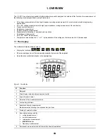
Страница 4: ...emperature measurement in C or F by linearisation of the voltage on the terminals of a K thermocouple 1 1 The display The multimeter s display allows users to Display the functions Show an analogue vi...

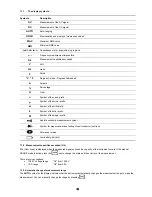
Страница 5: ...f the kilo prefix M Symbol of the mega prefix Audible continuity measurement symbol Symbol for measurement and testing of semiconductor junctions Permanent mode Low battery indicator 1 1 2 Measurement...

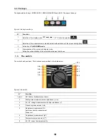
Страница 6: ...alues and display mode Activation or deactivation of the automatic instrument shut down 1 3 The switch The switch has 9 positions The functions are described in the table below Figure 3 the switch N F...

Страница 7: ...multimeter The switch is in the OFF position Turn the switch to the function of your choice All the display segments appear for a few seconds then the screen for the selected function is displayed The...

Страница 8: ...cted function position Every position except OFF is confirmed by a beep When the quantity V or A is selected the multimeter is in AUTO AC DC It then determines whether the measurement is an AC or DC m...

Страница 9: ...Hz When measuring a voltage with a frequency in excess of 150 Hz it is considerably reduced and therefore a significant error can occur In this case the position which uses the entire bandwidth should...

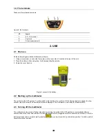
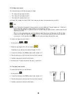
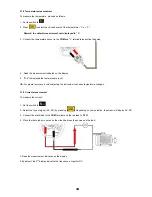
Страница 10: ...Read the measurement indicated on the display 5 O L is displayed if the circuit is open 3 1 5 Audible continuity measurement For audible continuity measurement proceed as follows 1 Set the switch to 2...

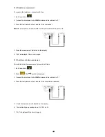
Страница 11: ...re the capacitance proceed as follows 1 Set the switch to 2 Connect the black lead to the COM terminal and the red lead to 3 Place the test probes on the terminals of the component 4 Read the measurem...

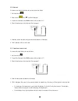
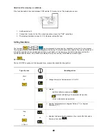
Страница 12: ...played the thermocouple is cut NB For greater accuracy avoid subjecting the instrument to sudden temperature changes 3 1 9 Current measurement To measure the current 1 Set the switch to 2 Select the t...

Страница 13: ...combined It is therefore possible to have min max peak relative or just relative In the same way the Hold mode does not stop the min max peak surveillance it only freezes the display Every push on a k...

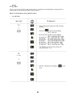
Страница 14: ...een displays 59 00 V range Auto When pressed the first time the screen displays 59 00 V manual range 60 V range the second time 59 0 V manual range 600 V range the third time 59 V manual range 1000 V...

Страница 15: ...15 15 In mode Type of press Resulting action short on exit from mode...

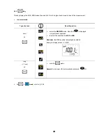
Страница 16: ...Type of press Resulting action short on enters the MAX MIN mode Note that is displayed in permanent operation to select the quantities for MAX or MIN Reminder the MAX quantity is displayed by default...

Страница 17: ...ition continues as a background task The bargraph continues to operate normally even in Hold In Hold the keys can be used exits from the mode long 2 sec on activates or deactivates the auto power off...

Страница 18: ...Resulting action short on freezes the display of each MAX MIN quantity displayed MAX MIN acquisition continues in the background This is indicated by blinking of the MAX MIN symbols If you press a se...

Страница 19: ...the reference conditions Uncertainties are given in X of the reading R Y counts D When the frequency exceeds 1 kHz apply the formula given in the tables X R Y x F kHz 0 4 R D where Reading R Digit D t...

Страница 20: ...60 V 6 60 V 0 01 V 3 at 50 V 600 V 60 600 V 0 1 V 3 at 500 V 1000 V 1 60 1000 V 1 V 1 2 R 3 D 1 2 L 0 5 x F kHz 0 4 L 3 D 40 Hz at 3 kHz 10 M 50 pF 1 42 at 1000 V 1 The display shows OL in excess of...

Страница 21: ...e conditions the input COM must not have been overloaded following the accidental application of voltage on the input terminals when the switch is on the or T position If this is the case the return t...

Страница 22: ...to 45 C 4 2 9 Temperature K thermocouple Special reference conditions Internal heating can be caused by the measurement of a high current over a long period overload of the COM input when the switch i...

Страница 23: ...r Voltage drop Protection 6 A 0 001 A 0 6 A to 6 A 40 Hz to 1 kHz 1 2 R 5 D 2 8 at 5 A 10 A 0 01 A 1 A to 10 A 40 Hz to 1 kHz 1 R 3 D 3 7 at 8 A 0 05 V mA Fast fuse 11 A 1000 V Admissible overload 10...

Страница 24: ...g 7 functions Resolution 6000 count double display Terminals 1 current connector 10A 1 cold point connector COM 1 connector for all measurements except amps Stand to hold the instrument in a position...

Страница 25: ...dards Emission class B Immunity Electrical discharge 4 kV on contact aptitude criterion B 8 kV in the air aptitude criterion B Resistance to radiated fields 10 V m aptitude criterion B Resistance to r...

Страница 26: ...DC 0 08 R 0 1 D 1 C 0 12 R 0 1 D 1 C 0 01 R 0 1 D 1 C 0 1 R 1 C 0 05 R 1 C 0 1 R 1 C 60 M 0 3 R 1 C F 0 2 R 0 1 D 1 C mF 0 6 R 0 1 D 1 C Hz 0 01 R 1 C Temp 2 C 0 05 R 1 C Temperature 10 C 18 28 50 C S...

Страница 27: ...rews retaining the cover located behind the unit 4 Replace the used battery 5 Screw the cover back on 5 3 Replacing the fuse To replace the large fuse size 10 x 38 type HRC 11 A 1000 V 30 kA proceed a...

Страница 28: ...d out on the instrument by a person not approved by the manufacturer An adaptation for a specific application not specified in the definition of the equipment or not indicated in the operating instruc...

Страница 29: ...044 727 75 55 Fax 044 727 75 56 UNITED KINGdOM Chauvin Arnoux Ltd Waldeck House Waldeck Road Maidenhead SL6 8BR Tel 01628 788 888 Fax 01628 628 099 MIDDLE EAST Chauvin Arnoux Middle East P O BOX 60 1...

Отзывы: