background image

12    

 DF II Series User Manual

ChANGING DISPlAY OPTIONS

From HOME display, select F2 DISPLAY key.  This places the gauge in DISPLAY SETUP MODE. 

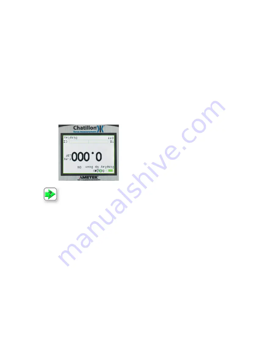
DISPlAY UP OR DOWN OPTION

The Display Up or Down option allows you to change the orientation of the display.

From HOME display, select F2 DISPLAY key.  The status line will read “Display Up Down”.  If the status 

line displays “ON”, the “Display Up Down” option is enabled.

To change the orientation, depress the F1 key (On or OFF).

If the “Display Up Down” option is ON, displayed information is presented upside down.  The function keys 

map to the function tags.

If the “Display Up Down” option is OFF, the feature is disabled.  The gauge displays information rightside 

up.

NoTE: 

 The Display Up or Down option only functions when the gauge is in the normal  

operating mode.  It does not operate in the setup modes.

DISPlAY bACKlIGhT OPTION

The Display Backlight option allows you to change 

the backlight level of the display.  This may be use-

ful in low or high light ambient environments and to 

save battery life.

The DISPLAY BACKLIGHT is the second option in 

the display setup mode.  

From the DISPLAY UP DOWN screen, depress the 

F3 DISPLAY key until “Display Backlight” appears 

on the status line.

Depress the F1 HIGH key or F2 LOW key to 

change the backlight level of brightness.

Selecting HIGH brightens the backlight setting.

Selecting LOW darkens the backlight setting.

Содержание DFE I

Страница 1: ...ustin Ft Worth NicolScales com 800 225 8181 Contact Us Nicol Scales Measurement is an ISO Accredited Calibration Company that has provided calibration repair and sales of all types of weighing and mea...

Страница 2: ...DF II Series User Manual 1 Part No NC003194 July 2013 DF II Series Digital Force Gauges for DFS II DFS II R DFS II R ND and DFE II Models User Manual...

Страница 3: ...This warranty is voidable if the purchaser fails to follow any and all instructions warnings or cautions in the instrument s Instruction Manual If a manufacturing defect is found AMETEK will replace...

Страница 4: ...PMENT IS USED IN A MANOR NOT SPECIFIED BY THE MANUFACTURER THE PROTECTION PROVIDED BY THE EQUIPMENT MAY BE IMPAIRED TO MAINTAIN ALL ASPECTS OF THE SPECIFICATION ONLY AMETEK APPROVED ACCESSORIES CONNEC...

Страница 5: ...Selecting high limit setpoint 34 Selecting low limit setpoint 35 Viewing load limit result 35 Using auto shutdown 36 Selecting time period 36 Activating auto shutdown 36 About gauge communications 37...

Страница 6: ...esult 65 Applying statistics to your break test result 66 View difference 67 Using filters 68 Display filter 68 Peak filter 68 Filter setup 68 Display filter setup 69 Peak filter setup 69 Using contac...

Страница 7: ...atillon DF II Series digital force gauges are battery powered precision instruments used to mea sure axial tensile or compressive forces The following models represent the DF II Series force gauges n...

Страница 8: ...n Rod1 SPK FMG 013A SPK FMG 013B Charger SPK DF2 UNIV RS232 Cable SPK DF RS232 Calibration Certificate Carrying Case SPK DF 118 Flat Adapter1 SPK FMG 011A SPK FMG 011B Hook1 SPK FMG 012A SPK FMG 012B...

Страница 9: ...Chatillon force tester MT150 SPK MT 0001 MT500 SPK MT 0001 LTCM 100 Direct Connect TT Tester NC002582 DF II Series MT150 SPK MT 0004 MT500 SPK MT 0004 LTCM 100 Direct Connect TT Tester NC002582 DF II...

Страница 10: ...and as power drains it will turn yellow to indicate a lower level of charge You may view battery life remaining by depressing the i key The gauge will display the estimated battery life based on curr...

Страница 11: ...numbers or to navigate in a downward direction or to the left UNITS Key A dedicated UNITS key is used to change the units of measure ZERO Key A dedicated ZERO key is used to zero a measured result or...

Страница 12: ...normal operating mode or setup mode It allows you to adjust the display backlight lighter or darker depending on your lighting conditions Hide Result This function operates in normal operating mode on...

Страница 13: ...Display Up Down option is OFF the feature is disabled The gauge displays information rightside up NOTE The Display Up or Down option only functions when the gauge is in the normal operating mode It d...

Страница 14: ...enable follow the same instructions as above with the F1 On key used to enable the function WARNING Disabling Auto Dimming will result in a reduction in battery life DISPLAY PEAKS The Display Peaks f...

Страница 15: ...ension Peak T PK Compression Peak C PK Zero and Taring Gauge The DF II Series gauge has a dedicated ZERO key for zeroing the measured result or for taring out the weight of accessories grips or fixtur...

Страница 16: ...ce gf grams force lbf pounds force kgf kilograms force N newtons Units Home Zero Enter i The ozf and gf units are available on DF II Series gauges with capacities of 100 lbf and below These units are...

Страница 17: ...be accessed by Pressing F3 More four times scrolling down to select Password Enable then pressing Enter The Status will show if the function is On or Off If Off Press the F1 key On to enable the Passw...

Страница 18: ...xially to the sample under test If the gauge is not secured properly you may get faulty reading or cause damage to the loadcell Affixing Adapters Fixtures Adapters and test fixtures should be mated to...

Страница 19: ...E you must clear all Saved Data from the gauge s memory This is to ensure that the gauge will correctly calculate statistics since results from different modes will cause erroneous statistics In DF II...

Страница 20: ...lied to the load sen sor A compressive load is indicated as a positive result A tensile load is indicated as a negative result The load bar graph will also indicate the load and direction of load that...

Страница 21: ...red FAIL two ways 1 If the gauge MODE is either T PK or C PK 2 If measured results are SAVED into memory Viewing Saved Result The DFE II will save up to 20 and the DFS II will save up to 100 measured...

Страница 22: ...when a peak result is displayed The gauge will also dis play either the High and Low Limits or the Nominal Value and Bandwidth The gauge will NOT dis play a PASS or FAIL for normal mode results Viewi...

Страница 23: ...the View display From Home select F3 More This will access the View display Select F1 Xmit to specify what you want to transmit You may transmit either the displayed result or all results saved in in...

Страница 24: ...Norm 9 3 9 Norm 10 4 5 Mean 4 0 S DEV 0 3 COV 7 13 Variance 0 1 Diff 1 v 2 0 00 2 v 3 2 68 3 v 4 14 83 4 v 5 4 20 5 v 6 7 21 6 v 7 4 05 7 v 8 12 66 8 v 9 12 64 9 v 10 13 86 Mode Result Value Units Nor...

Страница 25: ...e will transmit data With units Gauge will transmit result WITHOUT units Gauge will transmit result WITH units Transmit WITH UNITS Xmit W Transmit WITHOUT UNITS Xmit O NOTE The DFE II model does not h...

Страница 26: ...e F3 More key once This will access the View display To access the CLEAR option select the INFO key i key This will change the F2 Save key to F2 Clear Select F2 Clear to clear the displayed result Use...

Страница 27: ...he gauge will display green PASS or red FAIL depending on how the measured result compares to the setpoint range Example The DF II Series will display green PASS if the measured result is 11 2 lbf and...

Страница 28: ...FAIL depending on how the measured result compares to the setpoint range If the measured result is equal to or within the range calculated by the nominal value and user specified bandwidth the result...

Страница 29: ...ng Pass Fail Limits The factory default is Pass Fail Limits OFF To enable Pass Fail Limits from the Home display select F3 More twice This will take you to the Main Setup Menu display Use the navigati...

Страница 30: ...numeric value by tenths You select increments using the RIGHT and LEFT arrow keys on the navigation pod Selecting the RIGHT arrow increases the increment value Selecting the LEFT arrow decreases the...

Страница 31: ...e by the increment selected upon each key press Select enter when you have adjusted both the High and Low Pass Fail Limits to your desired setpoints Select NOMINAL VALUE Method Use the navigation pod...

Страница 32: ...ected upon each key press Note that the gauge will automatically calculate the High and Low Limits based on the Bandwidth en tered and the Nominal value Select enter when you are satisfied with your c...

Страница 33: ...ng Load Limits The DF II Series force gauge allows you to setup and apply LOAD LIMITS You may setup HIGH and LOW load limits Load Limits are useful for protecting your gauge or testing system from dam...

Страница 34: ...e will transmit a continuous data string to the attached TCD Series tester through the RS232 port When a High Limit is reached the DF II Series gauge will send a continuous string of to the tester The...

Страница 35: ...T select enter until you have adjusted both the High and Low Limits to your desired setpoints 0 lbf 100 lbf High Limit Compression Selecting Increments Increments are associated with the numeric value...

Страница 36: ...LOW Load Limit tag indicating that you are about to adjust this value Use the UP and DOWN navigation key to increase or decrease the Low Load Limit VALUE The value will increase by the increment selec...

Страница 37: ...own when there has been no keypad activity or communication activity from 10 minutes up to 480 minutes 8 hours Activating Auto Shutdown Automatic Shutdown may be activated from the Main Setup display...

Страница 38: ...orce gauge via the USB port To verify the USB connection is set up properly between the computer and the Chatillon DF2 force gauge go Control Panel Hardware and Sound Device Manager Ports COM LPT You...

Страница 39: ...To enable XMIT LIMITS position the arrow next to the XMIT LIMITS tag Select the RIGHT arrow on the navigation key to enable this feature ON Select the LEFT arrow on the navigation key to dis able this...

Страница 40: ...table below 1 TXD O RS 232 Transmitted Data 2 RXD I RS 232 Received Data 3 GND O Ground Digital Ground 4 O Clock Mitutoyo Clock 5 O Ready Mitutoyo Ready 6 I Request Mitutoyo Request 7 O Data Mitutoyo...

Страница 41: ...Peak Modes Normal Tension Peak Compression Peak R Resets the gauge zeroes all modes S N MODE CR LF or Sends currently selected mode TP MODE CR LF or Normal Tension Peak Compression CP MODE CR LF Peak...

Страница 42: ...ty may be setup from the Main Setup display From the Home display select the F3 More key twice to access the Main Setup display Use the UP and DOWN navigation keys to position the cursor arrow next to...

Страница 43: ...transmit ting the current displayed result or transmitting all results saved in the instrument memory Selecting the Xmit keys will send data through the gauge s output in the configured format to the...

Страница 44: ...Outputs and match the baud rate in the gauge to the baud rate for the printer Connecting a Mitutoyo Printer Connect the DF II Series gauge to a Mitutoyo printer using the optional Mitutoyo cable p n N...

Страница 45: ...of better than 0 1 full scale The flexible cable used with the SLC sensors are ideal for applications where access to the sample under test is limited The cable when fully extended reaches approximate...

Страница 46: ...ed and the measurement is too near the zero under 10 the measured results may indeed be inaccurate e g using a 100 lbf loadcell to measure a 10 lbf load Expected Recommended Load Capacity Model 50 225...

Страница 47: ...gauge with power still ON the gauge will display No Sensor If you connect a new sensor to the DFS II R ND with power still ON the gauge will display the last sensor that was recognized at power up It...

Страница 48: ...ng sure to properly seat the individual pins Once the sensor is connected secure the sensor by tightening the mounting screws Do NOT over tighten Finger tight torque is sufficient Turn the DFS II R ND...

Страница 49: ...d to tension One end is dedicated to compres sion n Use the proper capacity for your testing Ideally make sure that the expected mea sured load falls within the 20 to 80 range of the sensor capacity n...

Страница 50: ...C 0025 400 x 0 05 10 000 x 1 25 x 0 002 10 x 0 001 100 x 0 01 SLC 0050 800 x 0 1 25 000 x 2 50 x 0 005 25 x 0 002 250 x 0 02 SLC 0100 1600 x 0 2 50 000 x 5 100 x 0 01 50 x 0 005 500 x 0 05 SLC 0200 20...

Страница 51: ...re ate graphs or more detailed statistical analysis TCD WEDGE software features n automatic communication setup n automatic Microsoft Excel file generation n display language selection English German...

Страница 52: ...eraging test works identical to the Force Based method except it adds Time as a factor You may set the Time Value from 1 second to 999 seconds This gauge mode is rep resented and displayed as LAVt The...

Страница 53: ...toggle between the two available Load Average Types Selecting Increments Increments are associated with the numeric values displayed by the gauge during setup You select the increment you want to use...

Страница 54: ...DOWN navigation key to set the Preload Limit value Depressing the DOWN key will decrease the displayed value Depressing the UP key will increase the displayed value Depress ENTER to select Selecting...

Страница 55: ...key until the gauge displays LAVf for mode The LAVf label indicates that the gauge is setup to perform a Load Average test based on a force only No time Apply load to the measurement sensor Load shou...

Страница 56: ...you display T PK or C PK At the completion of a test you may record the following n Minimum Load equals Preload Value n Peak Load equals T PK or C PK n Average Load equals LAVf You may Transmit F1 Sa...

Страница 57: ...d to be 100 lbf and the Drop was setup as 80 the gauge will define the Break Load as 80 lbf If the maximum load was measured to be 50 N and the Drop was setup as 50 the gauge will de fine the Break Lo...

Страница 58: ...looks for a 95 Drop from the maximum load In this test you can determine the Break Detect Point which is the load that must first be achieved before the DFS II Series gauges begins to look for a 95 D...

Страница 59: ...Compression n TBK Break Tension n CBK Break Compression Selecting Increments Increments are associated with the numeric values displayed by the gauge during setup You select the increment you want to...

Страница 60: ...ge may never see a break The best way to establish the break point is through sample testing trials Break Point Sharp Break Method To set the Break Point in a Sharp Break setup establish the correct i...

Страница 61: ...II gauge will end the test If the gauge is used with a TCD tester the gauge will signal the tester at 95 lbf to stop the test A Percentage Break is a user defined percentage drop You may specify the D...

Страница 62: ...The DFS II Series gauge will display the following results and test parameters n 95 Drop Sharp Break Default value n Break Break Load expressed as STBk n Max Maximum Load Compress to Rupture Break A...

Страница 63: ...he mode indicator displays TBk The DFS II Series gauge will display the following results and test parameters n Drop user defined n Break Break Load expressed as TBk n Max Maximum Load Compress to Rup...

Страница 64: ...ugh the DFS II Series RS232 USB communication port or Bluetooth When you select the F1 Xmit key you will be pro vided with two options n Xmit W F1 n XmitAll F2 The F1 Xmit W key will transmit the curr...

Страница 65: ...or without Units n Peak Load with or without Units n Drop Value n Break Point Value n Pass or Fail Result n Pass Fail High Limit n Pass Fail Low Limit Information will be transmitted in a Row format E...

Страница 66: ...in memory If larger numbers of results are required you should use the Nexygen DF II Series Software The gauge will display the Result Number compared to the available results saved e g 1 of 100 Save...

Страница 67: ...rage of the number of results saved in memory In addition to the Mean value the gauge will also display the Maximum and Minimum values on which the Mean was calculated Select the F1 Xmit key to transm...

Страница 68: ...t Select F2 S Dev to calculate and display the next statistic Standard Deviation Select F3 More to go to the next statistical operand Mean View Standard Deviation Standard Deviation is displayed after...

Страница 69: ...lay update rate for the DF II Series is 10Hz The display data rate may be reduced to 4Hz maximum data averaging before values are displayed Adjusting the Display Filter affects the instantaneous force...

Страница 70: ...nge the Display Filter rate to 4Hz depress the UP or DOWN navigation key The display rate will change between 10Hz and 4Hz Select Enter when the desired rate is displayed Peak Filter Setup From the Di...

Страница 71: ...witch and will display the peak force that caused the switch to Open or break If the Pass Fail option is used the gauge will also display whether or not the force requirement was met and indicate eith...

Страница 72: ...saved in the gauge memory for statistical calculations Contact Closure Pass Fail The DFS II Series gauge s Pass Fail feature can be used with the Contact Closure Mode Pass or Fail limits may be confi...

Страница 73: ...Setup Contact closure is specified using the DFS II Gauge Setup menu From the HOME display press F3 More four times to get to the CONTACT CLOSURE option Use the UP or DOWN navigation key to cursor to...

Страница 74: ...re OPEN Type If this option is selected the DFS II Series gauge will freeze its display when a switch has been opened break Select F1 OPEN to specify the DFS II to look for a switch break Select F2 Ba...

Страница 75: ...cal Equipment for Measurement Control and Laboratory use Transducers with integrated or remote signal conditioning RoHS and WEEE Power Battery Nickel Metal Hydride or direct AC 120 230Vac Battery Life...

Страница 76: ...1 6 2 4 1 1 m m 1 0 3 2 UNF Mtg Holes 2 P la c es 3 0 3 7 7 0 m m 2 2 5 5 7 1 m m E 9 6 3 5 3 Gauge with Integral Load Cell Sensor Gauge with Remote Load Cell Sensor 10 32 1 5 10 32F 0 75 0 75 2 0 8...

Страница 77: ...76 DF II Series User Manual...

Страница 78: ...DF II Series User Manual 77...

Страница 79: ...78 DF II Series User Manual...

Страница 80: ...DF II Series User Manual 79...

Страница 81: ...80 DF II Series User Manual...

Страница 82: ...DF II Series User Manual 81...

Страница 83: ...82 DF II Series User Manual...

Страница 84: ...DF II Series User Manual 83...

Страница 85: ...m All rights reserved UK Lloyd Instruments Ltd Tel 44 0 1243 833 370 uk far general ametek co uk France AMETEK S A S Tel 33 0 1 30 68 89 40 general lloyd instruments ametek fr Germany AMETEK GmbH Tel...

Отзывы: