background image

39

SYMPTOM

POSSIBLE CAUSES

SOLUTIONS

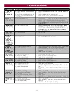
Gate opens, but
will not close with
transmitter or
Timer-to-Close.

a. Open control active

b. Vehicle loop detector active

c. Fire Dept input active

d. Timer-to-Close not set

e. Close Entrapment Protection Device active

a. Check all Open inputs for an active input

b. Check all vehicle detector inputs for an active detector

c. Check AC power and AC Fail option setting

d. Check if AC power is available. If no AC power, then running on

batteries and battery voltage must be 23.0 Vdc or higher. Charge
batteries by AC or solar power or replace batteries.

e. Check Fire Dept input

f. Check Timer-to-Close (TTC) setting

g. Check all Entrapment Protection Device inputs for an active sensor

Gate closes, but
will not open.

a. Vehicle loop detector active

b. Low battery with LOW BATT option set to

CLOSE

a. Check all vehicle detector inputs for an active detector

b. Check if AC power is available. If no AC power, then running on

batteries and battery voltage must be 23.0 Vdc or higher. Charge
batteries by AC or solar power or replace batteries.

Exit loop activation
does not cause
gate to open.

a. Exit vehicle detector setup incorrectly

b. Defective Exit loop detector

c. Low battery with LOW BATT option set to

CLOSE

a. Review Exit loop detector settings. Adjust settings as needed.

b. Replace defective Exit loop detector.

c. Check if AC power is available. If no AC power, then running on

batteries and battery voltage must be 23.0 Vdc or higher. Charge
batteries by AC or solar power or replace batteries.

Interrupt loop does
not cause gate to
stop and reverse.

a. Vehicle detector setup incorrectly

b. Defective vehicle loop detector

a. Review Interrupt loop detector settings. Adjust settings as needed.

b. Replace defective Interrupt loop detector.

Shadow loop does
not keep gate at
open limit.

a. Vehicle detector setup incorrectly

b. Defective vehicle loop detector

a. Review Shadow loop detector settings. Adjust settings as needed.

b. Replace defective Shadow loop detector.

Obstruction in
gate's path does
not cause gate to
stop and reverse.

a. Force adjustment needed

a. Refer to the Adjustment section to conduct the obstruction test and

perform the proper force adjustment that is needed.

Photoelectric
sensor does not
stop or reverse
gate.

a. Incorrect photoelectric sensor wiring

b. Defective photoelectric sensor

a. Check photoelectric sensor wiring. Retest that obstructing photoelectric

sensor causes moving gate to stop, and may reverse direction.

b. Replace defective photoelectric sensor. Retest that obstructing

photoelectric sensor causes moving gate to stop, and may reverse
direction.

Edge Sensor does
not stop or reverse
gate.

a. Incorrect edge sensor wiring

b. Defective edge sensor

a. Check edge sensor wiring. Retest that activating edge sensor causes

moving gate to stop and reverse direction.

b. Replace defective edge sensor. Retest that activating edge sensor causes

moving gate to stop and reverse direction.

Alarm sounds for 5
minutes or alarm
sounds with a
command.

a. Double entrapment occurred (two

obstructions within a single activation)

a. Check for cause of entrapment (obstruction) detection and correct. Press

the reset button to shut off alarm and reset the operator.

Alarm beeps three
times with a
command.

a. Low battery

a. Check if AC power is available. If no AC power, then running on

batteries and battery voltage must be 23.0 Vdc or higher. Charge
batteries by AC or solar power or replace batteries

On dual-gate
system, incorrect
gate opens first or
closes first.

a. Incorrect Bipart switch setting

a. Change setting of both operator’s Bipart switch settings. One operator

should have Bipart switch ON (operator that opens second) and the other
operator should have Bipart switch OFF (operator that opens first).

Alarm beeps when
running.

a. Expansion board setting

b. Constant pressure to open or close is given

a. Pre-warning is set to "ON"

b. Constant pressure to open or closed is given

TROUBLESHOOTING

Содержание LA400DCS

Страница 1: ...use in Class I II and III vehicular swing gate applications Visit LiftMaster com to locate a professional installing dealer in your area This gate operator is compatible with myQ and Security 2 0 accessories OPERATOR REQUIRES A LIFTMASTER EXTERNAL MONITORED ENTRAPMENT PROTECTION DEVICE BE INSTALLED IN ALL ENTRAPMENT ZONES OPERATOR REQUIRES A LIFTMASTER EXTERNAL MONITORED ENTRAPMENT PROTECTION DEVI...

Страница 2: ...ROUBLESHOOTING 34 Diagnostic Codes 34 Diagnostic Codes Table 35 Control Board LEDs 37 Troubleshooting Chart 38 APPENDIX 41 Bracket Types 41 Step 10 Solar Panels 42 Limit Setup with a Remote Control 46 REPAIR PARTS 47 Standard Control Box 47 Gate Operator Arm 47 WIRING DIAGRAM 48 Standard Control Box 48 ACCESSORIES 49 WARRANTY 51 TEMPLATE FOR POST BRACKET MOUNTING 52 When you see these Safety Symbo...
Страница 3: ...ehicular swing gate operator will operate only after installation of a minimum of two independent monitored entrapment protection devices in either the open or close direction If no entrapment zone exists in the other direction of gate travel then the inherent built into the operator is all that is required in that direction l Entrapment protection device types include inherent built into the oper...

Страница 4: ...from reaching over under around or through the gate to operate the controls Outdoor or easily accessible controls shall have a security feature to prevent unauthorized use Exception Emergency access controls only accessible by authorized personnel e g fire police may be placed at any location in the line of sight of the gate 9 The Stop and or Reset if provided separately must be located in the lin...

Страница 5: ...ct with a moving vehicular access gate A pedestrian gate shall not be incorporated into an automated vehicular gate panel 2 Specific Applications 2 1 Any non automated gate that is to be automated shall be upgraded to conform to the provisions of this specification 2 2 This specification shall not apply to gates generally used for pedestrian access and to vehicular gates not to be automated 2 3 Wh...

Страница 6: ...p 2 Flat Washer 5 16 1 Lock Washer 5 16 1 Pin 2 Keylock Cap Key 2 Carriage Bolt 3 8 x 5 15 16 2 Optional Accessories Push to Open Bracket Model 50 19503 If your application requires the gate to be pushed open a push to open bracket is required see Accessories Expansion Board Model K1D8387 1CC Large Metal Control Box for Solar Applications Model XLSOLARCONTUL Required for solar installations batter...

Страница 7: ...0 Degree Travel Time 15 18 seconds Maximum Travel Range 115 degrees Maximum Daily Cycle Rate 100 cycles day Maximum Duty Cycle 4 min on Operating Temperature 20 C to 60 C 4 F to 140 F Expansion Board Optional External Entrapment Protection Device Inputs non contact and or contact Main board up to 2 close entrapment protection devices and 1 open entrapment protection device Expansion board up to 3 ...

Страница 8: ...ermine the best device for your site needs Safety Entrapment protection devices are required to protect against any entrapment or safety conditions encountered in your gate application Install a warning sign two provided on the inside and outside of the property where easily visible Gate Gate must be constructed and installed according to ASTM F2200 standards refer to page 4 Gate must fit specific...

Страница 9: ...vel or it will not function properly l Make sure there is slack in the operator cable l The operator can be mounted on top of the gate frame l The operator must be installed at least 12 30 cm from the ground Don ts l DO NOT install upside down l DO NOT install next to sprinklers or any area that may expose the bottom of operator to water l DO NOT install on uphill or downhill gates l DO NOT instal...

Страница 10: ...rclockwise The operator is now in manual mode 3 Assemble gate post bracket by placing pull to open bracket on top of post bracket 4 Insert the bolt through both brackets and secure with washer lock washer and nut 5 Attach post bracket assembly to operator using pins and hairpin clips 6 Attach gate bracket to operator using pins and hairpin clips INSTALLATION ...

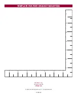
Страница 11: ...page of this manual under the center of the gate hinge point 3 Use a screwdriver or dowel rod to temporarily mark the location in front of the gate post OR Tape Measure Method 1 Close the gate 2 Place the measuring tape under the center of the gate hinge point and measure out 7 inches 17 8 cm 3 Use a screwdriver or dowel rod to temporarily mark the location of the first measurement 4 Measure 7 inc...

Страница 12: ... gate for reference Temporarily secure the gate bracket using a clamp 4 Align the pull to open bracket to a position as CLOSE AS POSSIBLE above the screwdriver or dowel rod 5 Insert hex bolt through pull to open bracket and post bracket and secure with washer lock washer and nut Test Gate Travel NOTE If gate does not open and close completely adjust the position of the gate bracket and mark new mo...

Страница 13: ...t to the gate post using hardware Gate Bracket The gate operator arm must be level Some installations may require additional reinforcement be installed on the gate 1 Drill holes in gate or reinforcement if necessary that are large enough for the gate bracket mounting hardware 2 Secure the gate operator to the gate using hardware not provided 3 Manually move the gate to verify that it opens and clo...

Страница 14: ... screws and open the control box 2 Select the mounting holes according to your application and remove the knockouts using a screwdriver and hammer 3 Secure the control box to mounting surface A Wall or Column Use the provided screws 4 B Post Use U bolts and rubber washers not provided to ensure a watertight seal Make sure the U bolts do not protrude more than 3 4 inch from the control box because ...

Страница 15: ...ng surface using the provided screws 4 Post Mount NOTE The post mount option is not recommended for the 33AH battery application 1 Open the control box The control box door may be removed by opening the door 90 Lift the door from the hinges and set aside until the installation is complete 2 The control box can be mounted to a post with U bolts refer to chart The knock out will accommodate a 3 8 di...

Страница 16: ...round Rod Use the proper earth ground rod for your local area The ground wire must be a single whole piece of wire Never splice two wires for the ground wire If you should cut the ground wire too short break it or destroy its integrity replace it with a single wire length 1 Install the earth ground rod within 3 feet 9 m of the operator 2 Run wire from the earth ground rod to the operator The earth...

Страница 17: ...ER LED will light NOTE The operator will time out of programming mode after 180 seconds 3 Press and release the LEARN button again on the primary operator The yellow NETWORK LED will light 4 Press and release the OPEN test button to assign this operator as network primary 5 Press and release the LEARN button on the second operator The green XMITTER LED will light 6 Press and release the LEARN butt...

Страница 18: ...in the junction box large enough for the watertight connectors 4 Mount the junction box within 3 feet 0 9 m of second operator 5 Route operator cable and extension cable through watertight connector nut and watertight connector 6 Insert the cables and watertight connectors into the holes in the junction box 7 Slide the connector nut onto the operator cable and extension cable 8 Remove terminals fr...

Страница 19: ... same side as this gate If there is no appropriate location on that side for the control box then mount the control box on the opposite side but connect the operator closest to the control box to the Gate 2 connector and the operator on the opposite side to the Gate 1 connector 1 The BIPART DELAY switch on the control board needs to be set to the ON position The illustration shows a dual gate conf...

Страница 20: ...rapment protection devices MUST be used with LiftMaster operators to meet UL325 requirements see Accessories l Test ALL entrapment protection devices after completing installation of the operator For testing instructions refer to the manual provided with your entrapment protection device Definitions ENTRAPMENT The condition when a person is caught or held in a position that increases the risk of i...

Страница 21: ...ut is for edge sensor entrapment protection for the close direction When an obstruction is sensed during gate closing the gate will reverse to the full open position disengaging the Timer to Close This input will be disregarded during gate opening OPEN EYES EDGE 2 Terminals The OPEN EYES EDGE input is for photoelectric sensor or edge sensor entrapment protection for the open direction When an obst...

Страница 22: ...e the junction box cover Ensure the wires are not pinched 8 Plug the J15 plug into the control board The control board will power up NOTE You may see a small spark when plugging the J15 plug into the board 9 Turn ON AC power to the operator OPERATOR POWER SOURCE DIRECT PLUG IN TRANSFORMER 120 VAC Wire Gauge 14 350 feet 107 m Wire Gauge 12 525 feet 160 m Wire Gauge 10 850 feet 259 m OR EXTERNAL PLU...

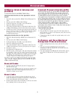
Страница 23: ...h electronic controls to make travel limit and force adjustments easy The adjustments allow you to program where the gate will stop in the open and close position The electronic controls sense the amount of force required to open and close the gate The force is adjusted automatically when you program the limits but should be fine tuned using the REVERSAL FORCE dial on the control board refer to Fi...

Страница 24: ... release the SET CLOSE or SET OPEN button depending on which limit is being set 5 Press and hold the MOVE GATE button to move the gate to the other limit 6 Press and release the SET CLOSE or SET OPEN button depending on which limit is being set The operator will exit limit setting mode 7 Cycle the gate open and close using the TEST BUTTONS This automatically sets the force 8 For dual gates set the...

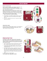
Страница 25: ...an be adjusted independently from the other by following steps 1 3 of the Initial Limit and Force Adjustment section Obstruction Test The operator is equipped with an inherent built in to the operator obstruction sensing device If the gate encounters an obstruction during motion the operator will reverse direction of the gate and then stop The following procedure will test ONLY the inherent built ...

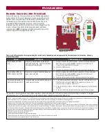
Страница 26: ...ton depending on the desired function 3 Press the remote control button that you would like to program The operator will automatically exit learn mode operator will beep and green XMITTER LED will go out if programming is successful To program additional Security 2 0 remote controls or remote control buttons repeat the programming steps above NOTICE This device complies with Part 15 of the FCC rul...

Страница 27: ...LED will light 2 Press and hold the LEARN button again until the green XMITTER LED flashes and then release the button approximately 6 seconds All remote control codes are now erased Erase Limits 1 To erase the limits press and hold the SET OPEN and SET CLOSE buttons simultaneously 5 seconds until both the SET OPEN and SET CLOSE LEDs blink rapidly and the operator beeps 2 Release the buttons and t...

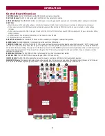
Страница 28: ...ARN Button The LEARN button is for programming remote controls and the network 7 TIMER TO CLOSE dial The TIMER TO CLOSE TTC dial can be set to automatically close the gate after a specified time period The TTC is factory set to OFF If the TTC is set to the OFF position then the gate will remain open until the operator receives another command from a control Rotate the TIMER TO CLOSE dial to the de...

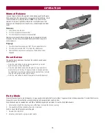
Страница 29: ...the control box and serves several functions l Press the reset button to stop a moving gate during a normal open close cycle like a stop button l Press the reset button once while the gate is in open position to disable the Timer to Close The gate will stay in the open position To restart the Timer to Close either press the reset button or activate the gate with a programmed remote control l Press...

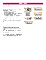
Страница 30: ...or bent in an awkward position Remove any obstructions Press the reset button to shut off the alarm and reset the operator After the operator is reset normal functions will resume The operator alarm will beep 3 times with a command if the battery is low Remote control Single Button Control SBC Functionality Once the remote control has been programmed the operator will operate as follows When gate ...

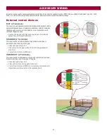
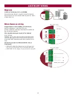
Страница 31: ...s a closing gate and holds open an open gate if maintained pauses Timer to Close at OPEN limit SHADOW 2 Terminals This input is used for external shadow loop detector when loop is positioned under the swing of the gate l Holds open gate at open limit l Only active when the gate is at the OPEN limit disregarded at all other times l Pauses Timer to Close at OPEN limit INTERRUPT 2 Terminals This inpu...

Страница 32: ...afeties and does not reset alarm condition Fire department open input 2 Terminals Acts as hard open Maintained input overrides ignores external safeties photoelectric sensor and edge pauses Timer to Close momentary input logic as single button control and safeties remain active re enables Timer to Close Accessory power 24 VDC MAX 500 mA 4 Terminals l SWITCHED Switched ON with gate motion and at th...

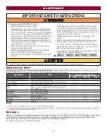
Страница 33: ...o gate travel l To reduce the risk of FIRE or INJURY to persons use ONLY LiftMaster part 29 NP712 for replacement batteries l SAVE THESE INSTRUCTIONS l ALWAYS wear protective gloves and eye protection when changing the battery or working around the battery compartment Maintenance Chart Disconnect all power AC solar battery to the operator before servicing The operator s AC Power switch ONLY turns ...

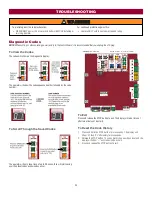
Страница 34: ... show the code sequence number followed by the code number To Scroll Through the Saved Codes The operator will only keep track of up to 20 codes then will start saving over the oldest codes as new codes occur To Exit Press and release the STOP button to exit The display will also time out after two minutes of inactivity To Reset the Code History 1 Press and hold the STOP button for six seconds The...

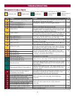
Страница 35: ...20V on a 24V system or less than 10V on a 12V system Make sure there is NOT a single 12V battery on a 24V system YES 43 Exit Loop Error Failure or missing loop SHORT or OPEN LiftMaster Plug in Loop Detector only Check loop wiring throughout connection May be a short in the loop or an open connection in the loop YES 44 Shadow Loop Error 45 Interrupt Loop Error 46 Wireless edge battery low Replace b...

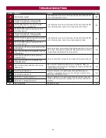
Страница 36: ...s and communication method between operators either wired bus or radio Ensure operator is powered May have to erase the wireless communication and reprogram the two operators YES 81 Open input EYE EDGE communication fault from other operator 82 Close input EYE EDGE communication fault expansion board Check the connections between the main board and the expansion board YES 83 Open input EYE EDGE co...

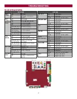
Страница 37: ... error ON Battery low MEDIUM BLINK 1 blink per second Battery critically low ACC PWR OVLD OFF OFF state ON Accessory overload protector opened INPUT LEDS SBC INPUT OFF Input inactive ON Input active BLINK Input active on other operator FIRE DEPT INPUT OFF Input inactive ON Input active BLINK Input active on other operator EXIT OFF Input inactive ON Input active BLINK Input active on other operator...

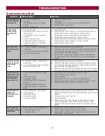
Страница 38: ...unting bracket c Gate is too difficult to move a Disengage the arm and ensure arm moves freely b Examine the hinge point where the arm mounts to the gate post Make sure that the arm housing does not hit or interfere with the gate post or mounting bracket Correct as necessary c Remove arm from gate and move gate manually Gate must move easily and freely through its entire range limit to limit Repai...

Страница 39: ...le loop detector a Review Shadow loop detector settings Adjust settings as needed b Replace defective Shadow loop detector Obstruction in gate s path does not cause gate to stop and reverse a Force adjustment needed a Refer to the Adjustment section to conduct the obstruction test and perform the proper force adjustment that is needed Photoelectric sensor does not stop or reverse gate a Incorrect ...

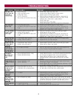
Страница 40: ... Disconnect all accessory powered devices and measure accessory power voltage should be 23 30 Vdc If voltage is correct connect accessories one at a time measuring accessory voltage after every new connection b Replace defective control board Quick Close not working correctly a Quick Close setting incorrect b Interrupt loop detector c Defective Expansion board a Check that Quick Close setting is O...

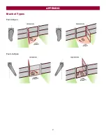
Страница 41: ...41 Bracket Types Pull to Open Push to Open APPENDIX ...

Страница 42: ...W12V l A maximum of six 10W solar panels Model SP10W12V Configuration of three sets of two 10W paralleled panels put in series l Two 7AH batteries 29 NP712 l Solar Battery Harness Model K94 37236 Solar Zones Solar panel recommendations are based upon the average solar radiation and the temperature effects on batteries in the given zones as shown on the map below Local geography and weather conditi...

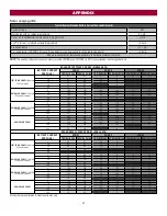
Страница 43: ...0 100 100 42 50 15 100 100 92 100 31 38 20 100 100 85 100 25 33 50 100 100 47 63 100 46 70 40W SOLAR PANEL Two 20W 12V panels in series 5 100 100 100 100 83 100 15 100 100 100 100 70 100 20 100 100 100 100 63 97 100 100 100 65 100 200 42 100 11 60W SOLAR PANEL 5 263 300 159 286 66 120 15 252 300 149 275 57 111 20 246 300 143 269 53 106 100 160 300 67 181 35 250 24 187 39 SOLAR GATE CYCLES PER DAY ...

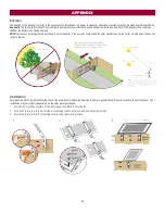
Страница 44: ...solar panel s in the summer could shade the solar panel s during the winter months when the sun sits lower in the sky Installation Solar panel s MUST be installed facing south Use a compass to determine direction Below are general instructions for installing the solar panel s Your installation may vary slightly depending on the solar panel purchased 1 Position the mounting bracket on the mounting ...

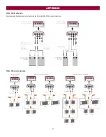
Страница 45: ...45 Wire the Batteries Solar panel applications require the Solar Harness Kit model K94 37236 see Accessories Wire the solar panels APPENDIX ...

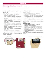
Страница 46: ...re set properly the operator will automatically exit limit setting mode Refer to the Adjustment section and follow the instructions for Fine Tune the Force and Obstruction Test Perform the Obstruction Test after every limit and force setting adjustment Adjust the limits If the limits have already been set the operator will exit the limit setting mode after resetting each limit Set the Close Limit ...

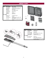
Страница 47: ...74 1 7AH Battery Harness K77 36541 Antenna LA400CONTUL Standard Plastic Control Box with Control Board K74 30941 ATC Fuse Kit Includes 20 Amp 1 15 Amp 2 GATE OPERATOR ARM ITEM PART NUMBER DESCRIPTION 1 LA400DC Primary Arm 2 41ASWG 442SA Release Lever 3 41ASWG 438SA Motor with Limit Switch Harness 4 41ASWG 0014SA Rear Connector5 5 41ASWG 489 Cable 24 V with Connector NOT SHOWN 041ASWG 0119 Release ...

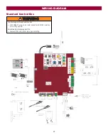
Страница 48: ...To protect against fire and electrocution l DISCONNECT power AC or solar and battery BEFORE installing or servicing operator For continued protection against fire l Replace ONLY with fuse of same type and rating WIRING DIAGRAM ...

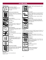
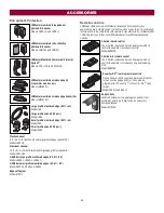
Страница 49: ...mall profile monitored edges 4ft 5ft 6ft Model S504AL S505AL S506AL Edge cutting tool Model ETOOL Remote controls LiftMaster offers a variety of LiftMaster remote controls to satisfy your application needs Single button to 4 button visor or key chain The following remote controls are compatible with operators manufactured by LiftMaster after 1993 Contact your authorized LiftMaster dealer for addit...

Страница 50: ...ty 2 0 compatible Model KPW250 Wire harness Between main control board and expansion board Model K94 34778 LiftMaster Cloud connected access protocol high capacity Model CAPXL Solar panel kit This kit is to replace or add a solar panel to the operator application 60W maximum for 24 Vdc operators and 30W maximum for 12 Vdc operators Requires a 33AH battery harness Models SP10W12V 10 Watt 12V and SP...

Страница 51: ... DURATION TO THE TWO YEAR LIMITED WARRANTY PERIOD SET FORTH ABOVE AND NO IMPLIED WARRANTIES WILL EXIST OR APPLY AFTER SUCH PERIOD Some states do not allow limitations on how long an implied warranty lasts so the above limitation may not apply to you THIS LIMITED WARRANTY DOES NOT COVER NON DEFECT DAMAGE DAMAGE CAUSED BY IMPROPER INSTALLATION OPERATION OR CARE INCLUDING BUT NOT LIMITED TO ABUSE MIS...

Страница 52: ...1 2 3 4 5 6 7 7 6 5 4 3 2 1 300 Windsor Drive Oak Brook IL 60523 LiftMaster com 2018 The Chamberlain Group Inc All Rights Reserved 01 39384B TEMPLATE FOR POST BRACKET MOUNTING ...

Отзывы: