background image

Appendix 


101 

1. 

Installing the Hard Drives 

To install the hard disks for RAID configuration please follow the following steps. 

1)  Make sure the jumper on each hard disk is set as Master 
2)  Install the hard disk into the drive bays. 
3)  Connect the Hard disk cables. 
4)  Connect the power cables for each hard drives to the appropriate power 

connector. 

5)  Boot the system and enter the BIOS Setup Utility. 
6)  Go to Integrated Peripherals menu and setup your IDE RAID devices. 
7)  Save changes and Exit Setup 


2. 

Enter the MBFastBuild™ utility


1) Boot up the system. If this is the first time you have booted with the 

FastTrak 20276 and drives installed, the Promise onboard BIOS will 
display the following screen. 


2) Press <

Ctrl-F

> simultaneously to display the FastBuild™ utility main 

menu. 

FastBuild (tm) Utility 1.xx (c) 1996-20015 Promise Technology, Inc. 


Auto Setup......................................................[ 1 ] 


View Drive Assignments ................................[ 2 ] 


View Array .....................................................[ 3 ] 


Delete Array ...................................................[ 4 ] 


Rebuild Array .................................................[ 5 ] 

Controller Configuration ................................[ 6 ] 


Press 1...6 to Select Option     

  [ESC] Exit 


MBFastTrak 133 (tm) “Lite” BIOS Version 2.00.X.XX 

(c) 1995-2001 Promise Technology, Inc. All Rights Reserved. 


No array defined…………………. 


Press <Ctrl-F> to enter FastBuild (tm) Utility or 

press <ESC> key to continue booting the system. 

[ Main Menu ]


[ Keys Available ]


Appendix 


102 

3. 

Creating a RAID 0 array (Performance) 

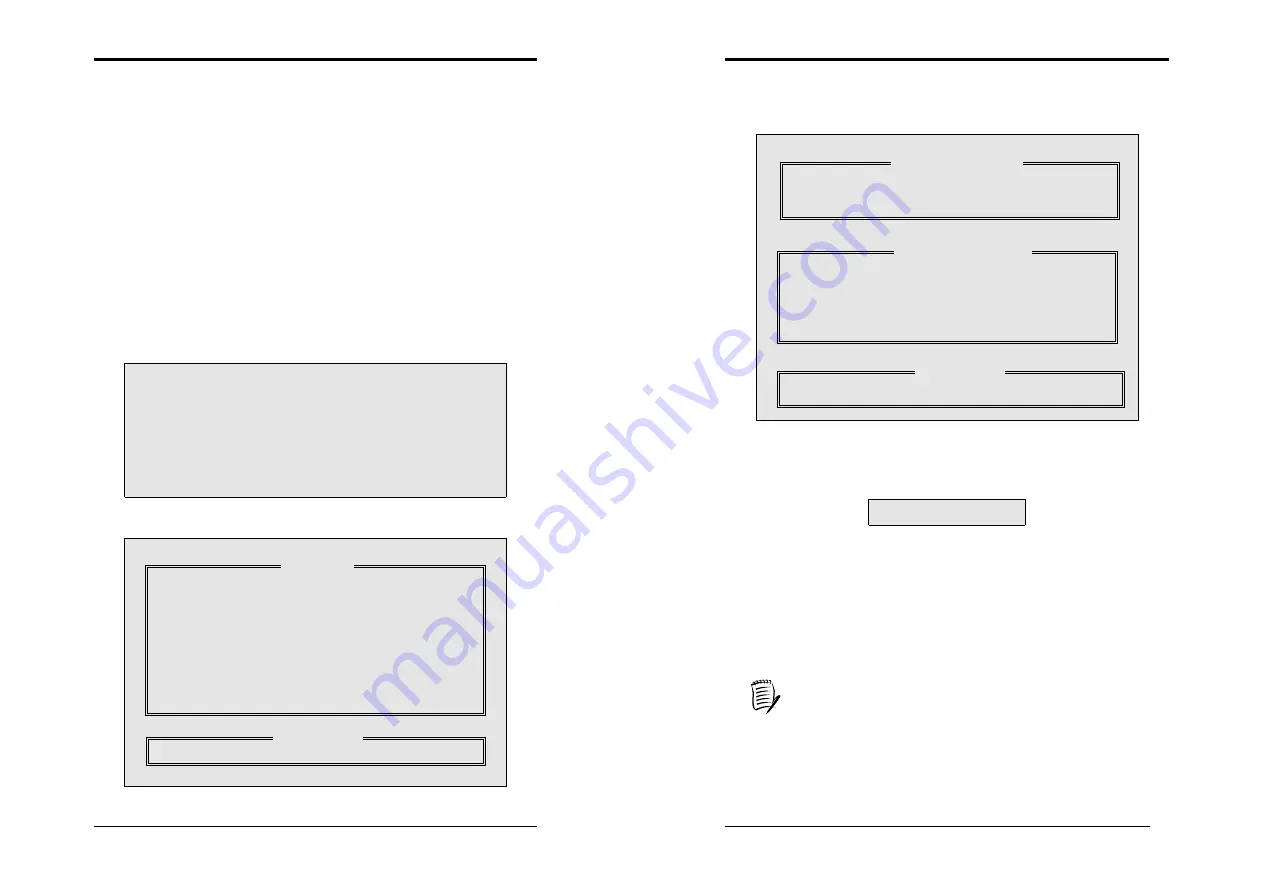
1)  In the FastBuild™ utility main menu, press [

1

] to select Auto Setup. The 

following screen will appear. 


2)  Use the arrow keys to go to the field 

Optimize Array for

 and select 

[

Performance

] with the space bar. The mode field will display [

Stripe

]. 

3)  After making a selection, press <

Ctrl-Y

> to save and create a RAID 0 

array. 

Array has been created…. 

<Press Any Key to Reboot>


4)  Reboot your system by pressing any key. During the boot process, the 

MBFasTrack20276 BIOS will check and display the disk array 
information. 

5)  Once the array is created, Use the FDISK utility to format the array as a 

single hard drive. 

6)  After you have formatted the arrayed drivers, install an operating system. 

The operating system will treat the RAID 0 array as a single drive unit. 

7)  Install the appropriate RAID driver. 


Depending on the operating system that you install, you might have to 

install the RAID drivers during or after the Operating System installaton. 


FastBuild (tm) Utility 1.xx (c) 1996-2001 Promise Technology, Inc. 


Optimize Array for: 


                                                          Performance 

            Typical Application to use                                                                  DESKTOP 


 Mode...........................................Stripe 

 Spare ................................................. 0 


Drives used in Array.......................... 2 


Array Disk Capacity................... 16126 


  [

] Up [

] Down   [

, Space] Change Option   [ESC] Exit   [Ctrl-Y] Save 


[Auto Setup Options Menu]


[ Array Setup Configuration ]


[ Keys Available ]


Содержание 9EJS1

Страница 1: ...device that complies with 47 CFR Parts 2 and 15 of the FCC Rules Operation is subject to the following two conditions 1 This device may not cause harmful interference 2 This device must accept any interference received including interference that may cause undesired operation This declaration is given to the manufacturer CHAINTECH EXCEL COMPUTER INC 4427 Enterprise St Fremont CA 94538 U S A http w...

Страница 2: ...his document and or the products associated with it at any time without obligation to notify any person or organization of such changes In no event will the manufacturer be liable for direct indirect special incidental or consequential damages arising out of the use or inability to use this product or documentation even if advised of the possibility of such damages This document contains materials...

Страница 3: ...egrated Peripherals 35 3 5 Power Management Setup 39 3 6 PNP PCI Configurations 42 3 7 PC Health Status 43 3 8 Frequency Voltage Control 44 3 9 Load Fail Safe Defaults 45 3 10 Load Optimized Defaults 45 3 11 Supervisor Password User Password Setting 45 3 12 Save and Exit Setup 45 3 13 Exit Without Saving 46 Chapter 4 DRIVER Setup 47 4 1 Intel IDE Bus Mastering Drivers Setup 47 4 2 Intel Applicatio...

Страница 4: ...i tasking operating systems On board Promise IDE RAID Controller Promise PDC20276 IDE RAID controller supports extra two Ultra DMA66 100 133 IDE ports with RAID 0 1 Chapter 1 2 USB 2 0 1 1 Host Controller One EHCI USB 2 0 Controller and 2 UHCI USB 1 1 Controllers Support total 6 USB 2 0 Ports USB1 1 compatible Support USB 2 0 High Speed Device 480 Mb s Transfer Rates On board Super I O Controller ...

Страница 5: ...Digidoc 80 Port POST Error Code List x 1 9 CD Box Package Include Driver CD x 1 Value pack 2002 x 1 Thiz Linux Asian and European Version x 2 10 Thermal grease pack x 1 11 Zenith Key Chain x 1 Chapter 1 4 1 3 CHAINTECH s Special Features CBOX 2 CHAINTECH s exclusive front panel Include USB 1 1 2 0 compliant Ext ports x 4 Earphone 3 5mm phone jack x 1 MIC in 3 5mm phone jack x 1 IEEE 1394 Ext port ...

Страница 6: ...Reader Imagemore AutoSave Zenith Key Chain Round Cable World s first 60cm Round Cable bundle brought to you by CHAINTECH an innovative streamliner ribbon cable provides better overall system stability and neatness Chapter 1 6 SPDIF kit and Fiber Optical Cable 6channel kit THIZ Linux CD IEEE 1394 USB2 0 RAID ...

Страница 7: ...Chapter 1 7 1 4 9EJS1 Motherboard Diagram Chapter 1 8 1 5 9EJS1 Motherboard Layout ...

Страница 8: ... overheating and possible burn out of your CPU In order to boot up with a newly installed CPU AC Power must be switched off before installation Chapter 2 10 2 2 Setting your CPU s Parameters Hyper Threading Functionality Requirement Content To enabling the functionality of Hyper Threading Technology for your computer system you require ALL of the following platform components CPU An Intel Pentium ...

Страница 9: ...ry module is deeply inserted into the socket 3 The plastic clip on each side of the DIMM slot will automatically close to hold the DDR Modules in place Chapter 2 12 2 4 Connector and Jumper Reference Chart Jump Connector Function Page PW 1 2 ATX Power Supply Connector 13 CN1A Front Panel Power Rest SPK etc Connector 14 FD1 Floppy Connector 15 IDE 1 2 IDE Hard Disk Connector 16 IDE 3 4 IDE RAID Con...

Страница 10: ...D in Suspend Mode While in Suspend mode the LED light on the front panel of your computer will flash Suspend mode is entered by pressing the Override Power Button pushing the Green button on your ATX case or enabling the Power Management and Suspend Mode options in BIOS s Power Management menu See section 3 5 Poly fuse Over Current Protection The poly fuse protects the system from dangerous voltag...

Страница 11: ...f the system case The reset switch allows you to restart the system without turning the power off 5 SPEAKER Speaker Connector This 4 pin connector connects to the case mounted speaker 6 HD LED IDE Activity LED Connector The IDE activity LED lights up whenever the system reads writes to the IDE devices FD1 Floppy Connector The motherboard provides a standard floppy disk drive connector that support...

Страница 12: ...PS2KB Wakeup option under Wake Up Events Pin Definition 1 2 Normal default 2 3 Clear CMOS Data Pin Definition 1 2 Disable default 2 3 Enable Chapter 2 18 in the BIOS s Power On Management screen You must also set this jumper s cap to pins 2 3 to use this function JP6 JP6A JP24 Enable Disable USB 0 1 2 3 4 5 Device Power ON Jumper JP6 USB 0 1 JP6A USB 2 3 JP24 USB 4 5 A USB keyboard hot key or a US...

Страница 13: ...ectors The board s management extension hardware is able to detect the CPU and system fan speed in rpm revolutions per minute The wiring and plug may vary depending on the manufacturer On standard fans the red is positive 12V the black is ground and the yellow wire is the rotation signal Connect the north bridge cooling fan to FAN3 The wiring and plug may vary depending on the manufacturer On stan...

Страница 14: ...SPDIF in out connector supports the digital audio This connector must be connected to the cable from an external device Connect the SPDIF bracket to this connector CN5 WOL Wake on LAN Connector Enable the Wake Up On LAN selection in BIOS s Power Management Menu to use this function The capability to remotely manage PCs on a network is a significant factor in reducing administrative and ownership c...

Страница 15: ...Blue LED Connector These features work entirely the same as the power indicator LED both shows the system s power status The only difference is that this one is blue while the other is red LED CN23 CN23A CBOX 2 Front USB Connector for USB 2 3 and 4 5 USB Port 2 3 CN23 USB Port 4 5 CN23A If you want to use a USB Keyboard you must enable the USB keyboard support function in BIOS s Integrated Periphe...

Страница 16: ...e system diagnostic monitoring display 80 PORT diagnostic display during POST at system boot up CPU temperature monitoring your system stays cool always DigiDoc is the doctor for your system Please refer to Appendix Digidoc 80 Port POST Error Code List for the detail Chapter 2 26 IR 1 IR Connector Select a UART Mode in BIOS s Integrated Peripherals menu the UART port to support IR function See sec...

Страница 17: ... MHZ Chapter 2 28 2 6 CBOX 2 Setup 1 Gently insert CBOX 2 into the regular 5 1 4 drive bay at the front of system chassis and securely tighten the side screws 2 Connect Motherboard to CBOX 2 Function Motherboard CBOX 2 USB 2 3 JP6A CN1 USB 4 5 JP24 CN2 Front Audio CN24 CN3 IEEE 1394 PT 6 7 8 CN4 Green Mode LED CN1A 2 pin 80 Port Display CN25 CN6 Remove CN24 Jumper Caps on motherboard 5 6 9 10 befo...

Страница 18: ...st time changing hardware in your system such as the HDD FDD video display or when the CMOS data has been lost or contaminated Choose the Standard CMOS Setup option from the CMOS Setup Utility menu Figure 3 1 to display the following screen Figure 3 2 Standard CMOS Feature Screen Date Time Set the date and time of the system Do not skip this function as all of your timed events such as power manag...

Страница 19: ...ppy drive assignment so that drive A will function as drive B and drive B will function as drive A Note that the boot sequence assignment mentioned directly above does not include booting from floppy drive B This function is useful if floppy drives B and A are of a different format and you want to boot from floppy drive B Boot up Floppy Seek This is a set up check for floppy power on after startin...

Страница 20: ...ly technical and beyond the scope of this manual Below are some abbreviated descriptions of the functions in this setup menu AGP Aperture Size MB This function determines the amount of system memory that is given to the AGP card Options range from 32MB to 512MB This is a dynamic memory allotment in that the AGP card will only use the amount of memory that it needs The remaining memory which is not...

Страница 21: ...ive interfaces support s prefetching for faster drive accesses Set to Disabled if this primary or secondary 5 IDE HDD Block Mode Block mode is also called block transfer multiple commands or multiple sector read write If your IDE hard drive supports block mode select Enabled to auto detect the optimal number of block read writes per sector the drive can support OnChip PCI Device This section provi...

Страница 22: ...ble modes 6 ECP Mode Use DMA This item automatically specifies a DMA channel 1 or 3 for the parallel port when it is set to EPP or ECP EPP mode 7 Game Port Address This item disables or assigns the address of the Game port Available options are 201 and 209 8 Mini Port Address This item disables or assigns the address of the Midi port Available options are 300 and 330 9 Mini Port IRQ This item spec...

Страница 23: ...e Display Power Management Signaling DPMS standard i e you have a monitor that supports Green features Use software supplied by your video subsystem to set video power management options Video off in Suspend This setting determines when the monitor enters power setting mode If set to Yes the monitor enters the power saving mode after the chosen event expires The Power Management function must be e...

Страница 24: ... default values for the motherboard Figure 3 6 PNP PCI Configurations Reset Configuration Data If you want to reset CMOS IRQ divide hardware device please selected to Enabled Resources Controlled By When set to Manual the system BIOS will not refer to the ESCD for IRQ DMA information Instead it will refer to the items in the setup menu for assigning IRQ DMA When set to Auto the system BIOS will re...

Страница 25: ...om the CMOS Setup Utility menu Figure 3 1 the screen below is displayed This sample screen contains the manufacturer s default values for the motherboard Figure 3 8 Frequency Voltage Control CPU Clock Ratio This feature allows user to manually configure your CPU clock ratio according to your processor s specifications CPU Clock This feature allows the system memory to run at CPU clock speed The de...

Страница 26: ...set to Setup a password is required to enter BIOS and change BIOS settings When the Security Option function is set to System a password is required to enter both BIOS and the computer s operating system for example Windows 98 found on the boot drive The third and fourth variables are user password and supervisor password selected in BIOS Figure 3 1 The main purpose of separating user and supervis...

Страница 27: ...your CD ROM driver or double click the CD drive icon in My computer to open the setup screen 4 1 Intel IDE Bus Mastering Drivers Setup 1 Click Intel IDE Bus Mastering Drivers 2 Click Next to start software installation Chapter 4 48 3 Click Yes to accept the license agreement 4 Please select Next ...

Страница 28: ...9 5 Please select Finish after restart 4 2 Intel Application Accelerator Setup 1 Click Ultra ATA storage driver Chapter 4 50 2 Click Next to start software installation 3 Click Yes to accept the license agreement ...

Страница 29: ...Chapter 4 51 4 Click Next to continue installation 5 Click Next to continue installation Chapter 4 52 6 Select click Finish to complete setup 4 3 Intel LAN Driver Setup 1 Click LAN Driver ...

Страница 30: ...ck Finish to complete setup Chapter 4 54 4 4 C MEDIA Sound Driver Setup This section provides information on installed audio devices by choosing Audio Drivers from the Setup Driver menu 1 Please select Audio Drivers 2 Please select Install Device Driver and Application ...

Страница 31: ...Chapter 4 55 3 Please select OK 4 Please select Next 5 Please select Next Chapter 4 56 6 Please select Next 7 Please wait select OK after restart 8 Select different channels according to you speakers ...

Страница 32: ...programs for the Sound card 5 2 Audio Rack Audio Rack includes 4 control panels C Media Mixer Volume CD Player MIDI Player MP3 Wav Player You can start the Audio Rack by selecting Start Program PCI Audio Applications Audio Rack CD Player Output Configuration MIDI Player Output Configuration MP3 Wav Player Configuration Mixer Setup Chapter 4 58 C Media Mixer Volume 1 Volume Control You can simply d...

Страница 33: ...ny digital media devices ex MD or DAT Advanced media devices SPDIF out only supports 44 1KHz and 48KHz High frequency rates Monitoring to analog out Monitors the SPDIF IN signal Digital SPDIF signals use the analog output through LINE OUT to make sound Validity Detection Select this option to detect and check the validity of the fiber signal Format Select between Normal and Reverse Device For devi...

Страница 34: ... increases the sensitivity of the microphone When designing the audio chip it limits the type of microphones that are available The audio chip only supports Active or Capacitive types of Microphone These microphones are those standard microphones we get on the market or those earphones that come with a microphone The one that Karaoke uses does not work on this chip Load Mixer Defaults This loads t...

Страница 35: ...Windows 95 98 Help Chapter 4 64 MIDI Player Output Configuration Setup 1 Under Win 95 98 3 options available for Output device Default MidOut Device MPU 401 Microsoft GS Wavetable SW Synth 2 Under Windows NT4 0 Only CMPCI MIDI device is available 3 Under Windows 2000 ME XP 3 options available for Output device Default MidiOut Device Microsoft GS Wavetable SW Synth MPU 401 Help ...

Страница 36: ...isk recording Please use default setting Recording Configuration 1 Recording Format Quality Name This is to setup the recording format There are 3 selections CD Quality Radio Quality and Telephone Quality The default setting is CD Quality Format Only PCM format is available while recording with audio card Attributes Enabling to setup recording quality The default is set at 44 100 kHz 16Bit Stereo ...

Страница 37: ...0 you are advised to read through this manual Please pay special attention to this chapter INSTALLITION For any enquiries you are welcome to contact our technical support team For the technical support services provided by Thiz Linux please pay attention to our latest news release To install Thiz Linux Desktop 6 0 please insert the CD ROM inside the box set to your computer s CD ROM drive to start...

Страница 38: ... side of the screen you will find the Online Help frame for various steps during installation If you want to hide it to free more space in the main frame you can click on the Hide Help button at the bottom left hand corner You can call back the Online Help frame by clicking on the Show Help button Chapter 6 70 Step 1 Language Selection for installation program The first step of installation is to ...

Страница 39: ...k experts only Select the type of partitioning that you want then press Next to proceed Chapter 6 72 If you select Have the installer automatically partition for you the following window will appear Please select how to allocate hard disk space Select one of the following items Disk Partitioning Ways Descriptions Remove all Linux Partitions on this system Installer will remove all Linux partitions...

Страница 40: ...llowable Drives Select in which hard disk will this partition be put Size MB Set the size of this partition Fixed size Fix the size of this partition Fill all space up to MB Ignore the value of Size The size of this partition will be the entered value minus all free space on the hard disk Fill to maximum allowable size Ignore the value of Size The size of this partition will be all free space on t...

Страница 41: ...rd disk to be partitioned Note fdisk is a hard disk partitioning tool in Text Mode Its functions are stronger than that of Disk Druid Don t select this option unless you are already familiar with fdisk After you have selected the options that you want press Next to proceed to Step 5 Step 5 Language Selection for the system After entering this step you will see the following screen In this step you...

Страница 42: ...m of compatibility we don t recommend users to select these options therefore normal users can press Next directly Note The more packages you select the more hard disk space is required Please check the size of system space occupied by the selected packages at the bottom of Chapter 6 78 the screen Step 8 About to Install Now everything is ready You can actually start the installation Once you pres...

Страница 43: ...Thiz Linux Desktop 6 0 by Simple Mode please enter any of the commands below and select the system language to be used in your desktop environment Command entered Language version to be installed en Thiz Linux Desktop in English fr Thiz Linux Desktop in French de Thiz Linux Desktop in German it Thiz Linux Desktop in Italian pt_PT Thiz Linux Desktop in Portuguese pt_BR Thiz Linux Desktop in Brazill...

Страница 44: ...Manual installation and configuration Enter any command below to install and configure Thiz Linux Desktop manually Hard disk partitioning mode can be selected as user desires Command entered Language shown in installation program linux text English linux text lang fr French linux text lang de German linux text lang it Italian linux text lang pt_PT Portuguese linux text lang pt_BR Brazilian Portugu...

Страница 45: ... the computer Select the type of keyboard you are using Since the system will auto detect the keyboard in use users only need to press Next in normal situation Step 3 Welcome When Thiz Linux installation program are being in use the screen will show this welcome address Press OK to proceed Fig text welcome gif Chapter 6 84 Step 4 Disk Partitioning Setup The system provides three ways of partitioni...

Страница 46: ...ux file system ext3 and reiserfs are journaling file system Even if the computer is shut down improperly the journaling file system can resume Chapter 6 86 the file system quickly There is no more waiting for hard disk scanning Allowable Drives Select in which hard disk will this parttition be put Size MB Set the size of this partition Fixed size Fix the size of this partition Fill all space up to...

Страница 47: ...ext Mode Its function is stronger than that of Disk Druid We don t recommend it to normal users unless you are familiar with fdisk Press OK to proceed when finished Chapter 6 88 Step 5 Language Support Select which languages the system will support You can use Space to select the required languages Multiple options permitted or press Select All to select all the languages Press OK to proceed Note ...

Страница 48: ...proceed Chapter 6 90 Note The more packages you select the hard disk space is required If need be you can check for the size of the selected packages at the bottom of the screen Step 9 Installation to Begin After all installation settings are done users will see the above screen indicating that installation can begin Press OK to begin copying and installing software Step 10 Installation in Progres...

Страница 49: ...tion all Linux partitions on the hard disk and the data on them will be removed If selecting the Simple Mode installation you will see the following screen Press OK and you will see the following screen After pressing OK Thiz Linux will be installed onto the hard disk immediately After the installation you will see the screen showing the installation is completed Now withdraw the CD ROM from the C...

Страница 50: ...o reboot Thiz Linux Desktop again After the recovering process completed users can see the following notices Recover Completed Please press OK to Reboot Press OK to reboot your machine b Uninstall System uninstallation means to remove Thiz Linux Desktop from the boot up system but at the same time retain all data on partitions If you want to remove partitions and the data on them you need to use f...

Страница 51: ...o chipset Chipset default values are MODBINable by OEM customers Appendix 96 16 Initial Early_Init_Onboard_Generator switch 18 Detect CPU information including brand SMI type Cyrix or Intel and CPU level 586 or 686 1B Initial interrupts vector table If no special specified all H W interrupts are directed to SPURIOUS_INT_HDLR S W interrupts to SPURIOUS_soft_HDLR 1D Initial EARLY_PM_INIT switch 1F L...

Страница 52: ...e 6D 1 Assign resources to all ISA PnP devices 2 Auto assign ports to onboard COM ports if the corresponding item in Setup is set to AUTO 6F 1 Initialize floppy controller Appendix 98 2 Set up floppy related fields in 40 hardware 73 Optional Feature Enter AWDFLASH EXE if AwdFlash is found in floppy drive ALT F2 is pressed 75 Detect install all IDE devices HDD LS120 ZIP CDROM 77 Detect serial ports...

Страница 53: ... technology RAID 0 striping or RAID 1 mirroring for high performance data security and fault tolerance RAID 0 Data striping this will optimize two identical hard disk drivers to read and write data in parallel interleaved stacks Identical drives can read and write data in parallel to increase performance and storage RAID 1 Data mirroring this will copy and maintain an identical image of data from ...

Страница 54: ...ESC key to continue booting the system Main Menu Keys Available Appendix 102 3 Creating a RAID 0 array Performance 1 In the FastBuild utility main menu press 1 to select Auto Setup The following screen will appear 2 Use the arrow keys to go to the field Optimize Array for and select Performance with the space bar The mode field will display Stripe 3 After making a selection press Ctrl Y to save an...

Страница 55: ... you want the disk image to be duplicated to another Yes No Y Create and Duplicate N Create Only Auto Setup Options Menu Array Setup Configuration Keys Available Appendix 104 9 Install the appropriate RAID driver Depending on the operating system that you install you might have to install the RAID drivers during or after the Operating System installaton b Creating a Security Array With An Existing...

Страница 56: ...vigation tips Arrow keys highlights through choices Space bar key allows to cycle through options Enter key selects an option ESC key is used to abort or exit the current menu Command options 2 6 on the FastBuild Utility s main menu are not required for setting up an array but they are useful for reconfiguring an array a Viewing Drive Assignments The View Drive Assignments 2 option in the Main Men...

Страница 57: ...ine Array Menu Drive Assignments Appendix 108 d Rebuilding Array The Rebuild Array 5 Menu option is necessary to recover from an error in a mirrored disk array You will receive an error message when booting your system from the FastTrak BIOS Drives MUST be replaced if they contain any physical errors Follow these steps BEFORE using the Rebuild Array menu option 1 On bootup the FastTrak20276 Startu...

Страница 58: ...act us if you have any problem about our products Any opinion will be appreciated For Asia Africa Australia and Pacific Island CHAINTECH COMPUTER CO LTD No 7 1 Chung Shin Rd Tu Cheng Taipei Hsien Taiwan ROC Tel 886 2 2268 9998 Fax 886 2 2269 7510 URL http www chaintech com tw E mail mail chaintech com tw For America CHAINTECH EXCEL COMPUTER INC 4427 Enterprise St Fremont CA 94538 U S A Tel 1 510 6...

Страница 59: ...it For Korea CHAINTECH KOREA CO Ltd 14F Mi Won B D Yeouido Dong 43 Youngdeunpo Gu Seoul Korea Tel 82 2 63323377 Fax 82 2 63323379 E Mail erin chaintechkorea com NOTE All rights are reserved for the products and corporate names logos that appear in this manual to their original owners CHAINTECH reserves all the rights to change this manual All information is subject to change without notice ...

Отзывы: