Quick Start Guide for 3680A/B Cable and Antenna Analyzer
2.4 Operating interface
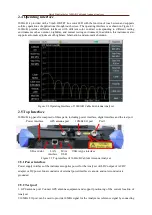
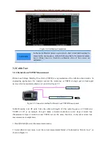
3680A/B is provided with a 7-inch HB TFT true color LED with the function of touch screen and supports
soft-key operations of applications through touch screen. The operating interface is as shown in Figure 2.2.
3680A/B provides different interfaces with different color contrast corresponding to different testing
environment such as outdoor, nighttime, and normal testing environment; In addition, this instrument also
supports automatic adjustment of brightness, hibernation, and automatic shutdown.
Figure 2.2 Operating Interface of 3680A/B Cable & Antenna Analyzer
2.5 Top Interface
3680A/B top panel is composed of three parts, including power interface, digital interface and the test port.
Power interface
GPS antenna port
10MHz I/O port
Port 1
SD card slot
LAN
interface
Mini
USB
USB A-type interface
Figure 2.3 Top interface of 3680A/B Cable & Antenna Analyzer
2.5.1 Power interface
Power supply interface of the instrument supplies power for the Analyzer with DC output of AC-DC
adapter or DC power. Inner conductor of external power interface is anode, and outer conductor is
grounded.
2.5.2 Test port
1. GPS antenna port: Connect GPS antenna equipment and support positioning of the current location of
Analyzer.
2.10MHz I/O port: can be used to provide 10MHz signal for the Analyzer as reference signal by connecting


