Quick Start Guide for 3680A/B Cable and Antenna Analyzer
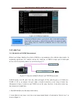
press
【
Marker
】
to turn on marker function, so that you can check the return loss conditions of the cable
at each frequency.
CAUTION
3.2.2 Cable Loss Measurement
Cable loss refers to the energy consumed by cable in the process of signal transmission, which is generally
represented by average value. During the test, the cable loss is usually measured by the following
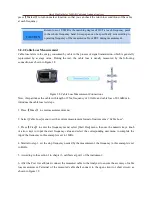
connection, as shown in Figure 3.8.
Figure 3.8 Cable Loss Measurement Connections
Now, this part takes the cable with length of 25m, frequency of 2.1GHz and cable loss of 0.36dB/m to
introduce the cable loss test steps.
1. Press
【
Meas
】
to enter measurement menu;
2. Select [Cable Loss] menu to set the current measurement format of instrument as “Cable Loss”
.
3. Press
【
Freq
】
to enter the frequency menu; select [Start Freq] menu, then use the numeric keys, knob
or arrow keys to input the start frequency value and select the corresponding unit menu to complete the
input; the frequency in this example is set to 1MHz.
4. Similar to step 3, set the stop frequency needed by the measurement; the frequency in this example is set
to 4GHz.
5. According to the section 1 in chapter 3, calibrate at port 1 of the instrument;
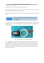
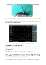
6. After the Port 1is calibrated, connect the measured cable to the Analyzer to ensure the accuracy of cable
loss measurement. Terminal of the measured cable shall connect to the open circuit or short circuit, as
shown in Figure 3.9.
Return loss or VSWR is the matching degree of DUT at each frequency point
in the whole frequency band. Sweep span can be specifically set according to
operating frequency of the measured cable or DUT during measurement.


