Quick Start Guide for 3680A/B Cable and Antenna Analyzer
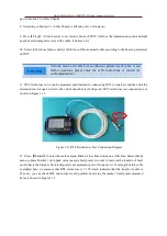
Figure 3.13 Antenna Measurement Connection Diagram
Make corresponding adjustment on the displayed amplitude according to amplitude set-method described
in section 3.5; then press
【
Marker
】
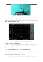
to turn on the marker function, so that you can see the VSWR
situation of antenna at each frequency. Through observation we can find that VSWR of antenna is smaller
near 2,100MHz, with minimum at 2,104MHz.
Figure 3.14 VSWR Test of Terminal Antenna TZD-P021Z05-195
3.4 Universal Devices and Parts Test
Addition to cable and antenna test, 3680A/B can also be used for testing the attenuation, cable connectors,
cable joints, etc. This part will measure the return loss of 10dB attenuation, as an example, with
operations as follows:
1. Press
【
Meas
】
to choose “Return Loss” as the measurement format of Analyzer.
2. Press
【
Freq
】
to set measurement range of Analyzer according to the working frequency range of
attenuator; if the frequency range of attenuator is not clear, users can measure the return loss/ VSWR
according to the system default frequency range (1MHz ~ 4GHz).
3. As the attenuator to be measured has interface with diameter of 3.5mm, N-3.5mm adapter needs to be


