10
CET Electric Technology
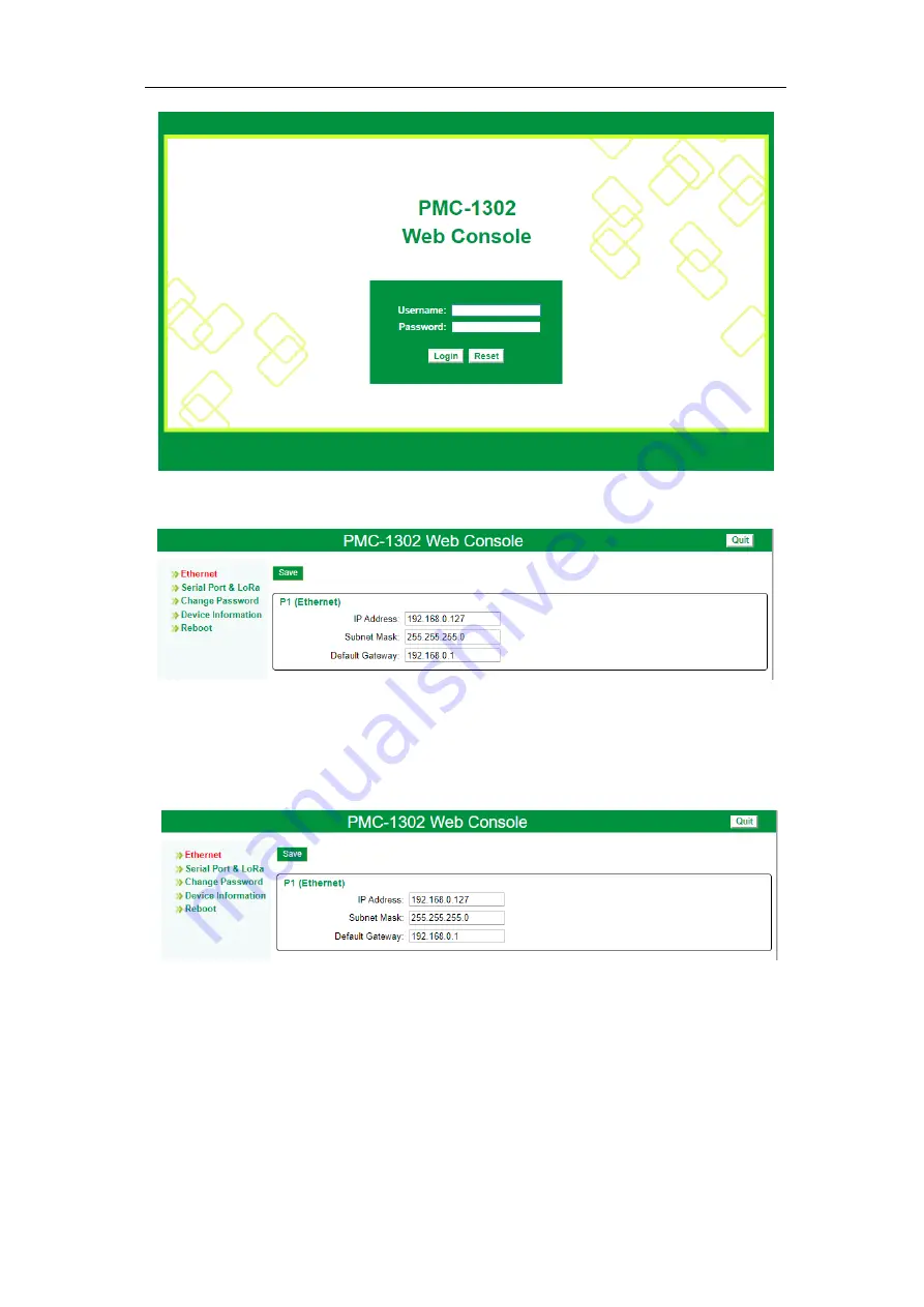
Figure 4-3 Login Interface
5)
Once the log-in credentials are confirmed, the following page appears.
Figure 4-4 Basic Settings
4.2 Ethernet
The
P1 (Ethernet)
port’s settings can be configured here based on the actual situation. Click
Save
to
confirm your changes. Please be reminded that the
IP Address
and
Default Gateway
for the Ethernet
port should be in the same subnet.
Figure 4-5 P1 Settings
4.3 Serial Port & LoRa
The PMC-1302-3 comes standard with two RS-485 ports (P2 and P3) and an optional LoRa wireless
port (P4). All setup parameters such as
Baudrate
,
Data Bits
,
Parity
,
Stop Bits
,
IP Port
and
Timeout
can be configured here to match the settings of the downstream RS-485 devices. Please be reminded
that the
IP Port
number of the Serial Gateway feature for P2 (default = 20001) and P3 (default =
20002) should be different. Click
Save
to confirm your changes. The following table shows the setup
parameters for P2, P3 and P4. Most setup parameters are basic and self-explanatory.
Please note that the
Packet
Timeout (s)
parameter refers to the timeout setting for the IP connection
instead of the serial or LoRa connection, meaning that the IP connection will be closed if there are no


