16
Section 1 - Outdoor Furnace Installation
Optional Gas-fired Wood Ignition Burner
An optional Gas-fired Wood Ignition Burner Kit (p/n
2500000) may be installed to light and automatically
relight the wood. Installation instructions are provided
with the kit.
Purging Air from the System - Manual Air
Bleeders
Manual air bleeders may be installed in the high points
of the water lines where air may get trapped and cause
circulation problems. Water can be pumped to levels
higher than the outdoor furnace as long as the pump is
pushing the water to the higher level and there are no air
leaks in the system. Additionally, air should be purged
from the system using pressurized domestic water and a
hose with two female ends (see Fig. 17 and 35).
WARNING
The outdoor furnace vent cap must fit loosely
on the vent opening. Do not force the cap down
or try to seal it tightly onto the vent pipe. Do not
extend or restrict the vent pipe or opening. DO
NOT ALLOW THE OUTDOOR FURNACE TO BE
PRESSURIZED.
If any auto float vents are present in the system, they
must be capped off tightly to prevent air from entering
the system.
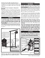
Fig. 17
NOTE: See the Hydronic Component Selection
Guide (p/n 2482) for more detailed information.
WATER HEATER INSTALLATION
WARNING
DO NOT disable or remove any safety reliefs or
controls. Turn off the power to the water heater
before installation.
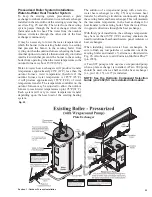
When installing a domestic hot water heat exchanger,
the hot supply line from the outdoor furnace should be
plumbed first to the water heater heat exchanger and
then to the balance of the heating system.
A manual 3-way valve may be installed so that during
the non-heating season, the water heater may be operated
without operating the entire heating system (see Fig.
20). A tempering valve (or thermostatic mixing valve)
is to be installed in the hot water outlet from the water
heater. Install a tee in a fitting on the top of the water
heater (see Fig. 18) for the hot water heat exchanger.
NOTE: If the water heater has been in service,
flush the water heater prior to installing the hot
water heat exchanger. Anode rod residue or other
sediments in the water heater may plug the heat
exchanger.
NOTE: Some gas water heaters are equipped with
a high water temperature probe that is connected
to the gas valve. When the water temperature
exceeds the high limit, the gas valve enters a
non-resettable lock out condition. This requires
replacement of the entire valve. The installer must
determine if this type of valve is present before
installation of a water-to-water heat exchanger.
CAUTION
Costly maintenance may be incurred if steps
are not taken during installation to reduce or
eliminate the possibility of the water temperature
in the water heater exceeding the high limit.
Fig. 18
H
C
M
R
NOTE
Use softened water if
water has a high mineral
content to avoid plugging
the heat exchanger.
NOTE
Installer must comply
with all applicable codes
and regulations.
NOTE
Outdoor furnace water
temperature setpoint
should be set at 185˚F
(85˚C) minimum.
NOTE
A pump must be installed
in the hot supply line
between the outdoor
furnace and thermostatic
valve.
NOTE
If outdoor furnace is not
being used for an
extended period of time
to heat water, this valve
should be closed to
prevent heat loss from
the water heater through
the side arm exchanger.
Hot Supply from Pump
on Outdoor Furnace
Return to Outdoor Furnace
Thermostatic Valve
Water-to-Water
Heat Exchanger
Bypass Line
Thermostatic
Mixing Valve
This horizontal assembly
must not exceed a height
of 4 inches (10 cm) above top
of water heater.
Hot Supply
For illustration purposes
only, water heater styles
may vary.
© 2015 Central Boiler
Existing
Water
Heater
1"
Central
PEX
®
Optional Bypass
Valve
Содержание e-Classic 1450 IR
Страница 17: ...15 Section 1 Outdoor Furnace Installation...
Страница 29: ...27 Section 1 Outdoor Furnace Installation Fig 30 Fig 31...
Страница 30: ...28 Section 1 Outdoor Furnace Installation Fig 32 Fig 33...
Страница 66: ...64 E CLASSIC 1450 WIRING DIAGRAM Section 6 General Information...
Страница 67: ...65 Section 6 General Information E CLASSIC 1450 WIRING DIAGRAM OPTIONAL POWER IGNITION...
Страница 69: ...67 NOTES...
Страница 70: ...68 NOTES...
Страница 71: ...69 NOTES...

