6
ENGLISH
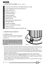
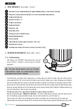
2. PUMP DESCRIPTION
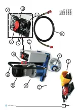
(Ref. to Fig. 1, page 3)
SOCKET
FOR
CONNECTING
THE
REMOTE
HAND
/
FOOT
PEDAL
CONTROLLER
MAINS
CABLE
(
PLUG
2
PHASES
+
EARTH
)
PROTECTION
FUSES
ON
-
OFF
SWITCH
I
/
O
QUICK
RELEASE
FEMALE
HYDRAULIC
COUPLER
TRANSPORT
HANDLE
ALARM
LED
ELECTRIC
MOTOR
HYDRAULIC
PUMP
/
OIL
RESERVOIR
REMOTE
HAND
CONTROLLER
REMOTE
FOOT
PEDAL
CONTROLLER
OIL
RELEASE
/
EMERGENCY
BUTTON
ELECTRICAL
PANEL
3
METRE
(
9.8
ft
)
HIGH
PRESSURE
FLEXIBLE
HOSE
3. INSTRUCTION FOR USE
3.1) Setting up
– Carry the pump using the handle (IM) and place
on a fl at, stable surface in a dry position.
B
EFORE
OPERATING
THE
PUMP
FOR
THE
FIRST
TIME
,
REPLACE
THE
TRANSPORT
CAP
WITH
THE
WORKING
CAP
SUPPLIED
.
– To avoid oil leakage during transportation, the
pump is equipped with an hermetically sealed cap which must be replaced with the working cap
supplied, for correct operation.
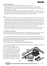
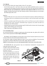
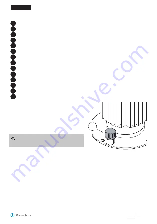
– Remove the transport cap and replace it with the orange working cap (TL) complete with dipstick
for oil level verifi cation, tighten fi rmly.
– Check that the nominal supply voltage corresponds to the value shown on the pump label then
connect to the mains: ON-OFF switch (IG) will light, indicating connection to mains elettricity.
The pump must only be connected to correctly earthed sockets.
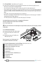
– Remove “
REMOTE CONTROL
” protective cap, connect the remote hand controller to the socket
(C) (see Fig. 4 page 35): tighten the plug (CP) by turning the bezel (G) clockwise until it locks.
– Connect the fl exible hose (TF) to the hydraulic head and to the corresponding female coupler
(IR) on the pump (see Fig. 4 and 5).
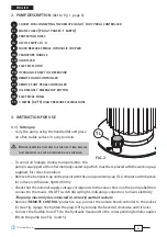
TL
FIG. 2
C
C1
F
IG
IR
IM
LA
MT
PO
PC
PF
PS
QE
TF
Содержание CPE-1
Страница 4: ...4 IM FIG 1 PUMP POMPE PUMPE BOMBA POMPA IR TF CA MT QE PO LA C IG PS F PF PC...
Страница 37: ...37 FIG 6 TL FIG 7 TV...
Страница 38: ...38 C2 C1 SE R RC RL TR PR EV FIG 8...


