


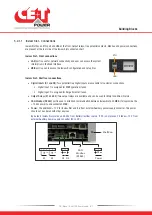


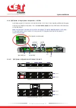
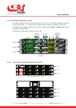


5.2.1.1 Inview Slot - Connections
Inview Slot has an ETH port and USB at the front. Output relays, free potential contacts, Modbus and power connections
are present at the rear side of the Inview Slot connected shelf.
Inview Slot - Front connections
•
LAN
port is used for network connectivity and user can access the system
information in the Web Interface.
•
USB
port is used to access the Inview S configuration and setup files.
Inview Slot - Shelf rear connections
•
Digital Inputs (D1 and D2):
Two potential free Digital Inputs are available for customer connections.
Digital Input 1 is assigned for MBP operation if used.
Digital Input 2 is assigned for Surge Arrester if used.
•
Output Relays (K1 and K2):
Two output relays are available and can be used for Major and Minor Alarms.
•
CAN Modbus (RS485)
port is used to establish communication between Inview Slot and MBB. It also provide the
+12 Vdc power to one connected MBB.
•
Power:
The addi12 V for Inview Slot and it is from external Auxiliary power supply converter. This power
should not be shared with other devices.
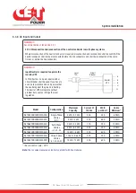
By default, Inview Slot works on 48 Vdc from battery/rectifier source. If DC is not present, it takes +12 V from
external Auxiliary power supply converter (AC to DC).
K1
K2
NO
NO
NC
NC
C
C
Power
PE
D1 D2
CAN
Modbus
(RS485)
Shelf Rear
ETH
USB
Building Blocks
16
- Bravo 10 - 48/120 - User manual - v1.1
Содержание BRAVO 10 - 48/120
Страница 59: ......