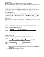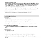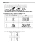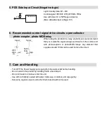
When the luminosity of light fluctuate due to excess amount of noise, please contact CCS.
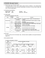
General Precautions Regarding to External Control
1. Bit Parallel Input Voltage
The input voltage is 1.35V maximum for “LOW” and 3.15V minimum for “HI”. Faulty operation
may occur if a open collector output is two-stage, and a surge absorbing diode connected in series.
Because the residual voltage goes up as high as 1.5V when the power is turned on. Meanwhile,
the voltage may drop (pull-up resistance x IL) and “HI” can no longer be maintained if the leakage
current (IL) is high when the open collector turns off.
2. Controlling
Output Units
(2-1) TTL/CMOS Output Units
The load voltage often ranges from 10.2 to 26.4V DC when sequencers use general-purpose
transistor output units. TTL/CMOS output units are ideal for this application because they operate
on +5 V and their residual voltage is guaranteed never more than 0.4 V.
(2-2) Separate Power Supply Control
A multi-bit output unit that is used to control both the PD power supply and the power system drive
unit makes the power system susceptible to noise because of the wiring involved. Provide a
separate power supply control unit to isolate the power supply from the power system.
3. Entry
Sequence
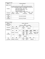
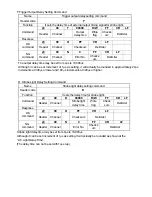
The setup and hold time takes 100
µ
s and the write pulse width is 1ms for the data entry sequence
described in this instruction guide. These figures, however, do not include the control circuit
ON/OFF response time or delay time variations between output channels. The PLC device and
photo coupler output for image processing also have relatively slow ON and OFF response times of
0.5ms and 1ms, respectively. Therefore, all the factors such as power supply setup time, hold time
with the output circuit response time, and delay time variations between channels, must be
considered in data entry.
4. Writing Light Intensity Data
There are some applications where light intensity data is written once when the power is turned on
and thereafter offer only lighting ON/OFF control. It is always safer to write light intensity data
every time even in those applications if the processing time allows it.
5. Wiring and Safety Measures
(5-1) Ground Wire
Wire the COM (GND) from the Output Unit directly to the power supply. Otherwise noise becomes
a factor and faulty operation is likely to occur. This happens because the GND level is raised by
COM current from somewhere other than the power supply if the COM (GND) is relayed by wiring it
to a terminal block and then branched it off for image processing, motor valve control, or the PD
power supply.
(5-2) Measures to Prevent Faulty Operation
If synchronization with motors, valves or other peripheral devices leads to faulty operation, then
move the external control line, lighting extension cable, or power supply away from the motor,
valve, or respective drive line causing the problem. Other possibilities for improving noise protection
include adding a ferrite core near the power supply unit or using shielded cable, twisted pair cable,
or cable with high EMI noise immunity.
Содержание PDS-30
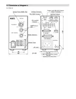
Страница 14: ...8 Dimensional diagrams 8 1 PDS 30 Light ...

