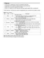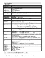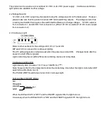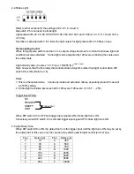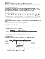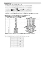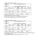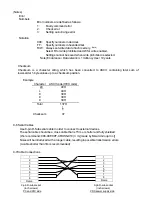
(5) Other I/O and Voltage Levels
The same ON/OFF signal (B11) and trigger signal (B12) that are input from the terminal block signals
can be input from the D-sub connector. With strobe light, the delay trigger signal (B13) that is used to
synchronize the external device set via RS-232C and the pulse light signal (B14) that is used to
confirm light are output at active LOW (5 V-CMOS level).
The pulse width of the delay trigger signal is always 100µs regardless of the pulse width of the trigger
input. The bit-parallel control signal is a 5V-CMOS level input (LOW: 1.35V max.; HI: 3.15V min.)
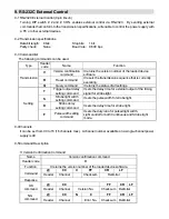
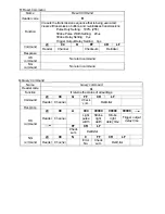
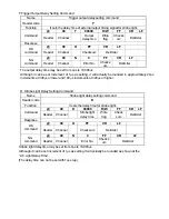
2-7 RS-232C External Control
Refer to 9.RS-232C External Control for details on external control via RS-232C.
3. Operating Instructions
3-1 Connection
Turn the power off.
Connect the LED light cable to the output connector on the power supply back panel.
Ground the FG terminal of the 10-W model with 0.5 to 1.25 sq wire (AWG20 to AWG16).
Connect power cord to wall socket.
When using external control, the control signal should be connected to the back panel connector.
3-2 Operation and Output Voltage Settings
It sets the mode selector DIP switch on the front panel and the voltage selector switch on the back
panel.
3-3 Turn the power on.
Turn ON the Power switch.
3-4 Light Control
In manual mode, the light intensity can be controlled with the coarse and fine rotary dials.
The pulse width can be set for strobe light in this mode from the pulse width setting switch.
Note: Press the test button on the front panel to manually check the strobe when strobe light is
selected.
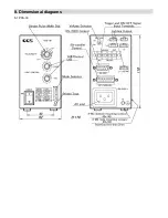
Содержание PDS-30
Страница 14: ...8 Dimensional diagrams 8 1 PDS 30 Light ...


