01/2001, CATTRON
- THEIMEG
TM
Section 3, Page 9
Operating Procedure – PS Controller
, continued.
WARNING:
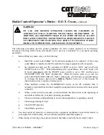
ON CAB AND REMOTE OPERATED CRANES OR CARRIERS AN AUDIBLE
OR VISUAL WARNING MEANS SHALL BE PROVIDED. IN ADDITION,
ALL EQUIPMENT SHALL HAVE AUDIO OR VISUAL ALARM
INDICATIONS MEETING GOVERNMENTAL REQUIREMENTS. FAILURE
TO IMPLEMENT THIS WARNING MAY RESULT IN PERSONAL INJURY
OR DEATH TO PERSONNEL AND DAMAGE TO EQUIPMENT.
CAUTION:
All control functions will be stopped if the PS Controller is used or left standing
in an upright position during heavy rain, or in hostile environments where water
could fill the top of the controller and cover the ‘i-Key’. To resume control
functions, simply invert and shake the controller to remove excess water. There
is no need to remove the ‘i-Key’. Ideally, to prevent such occurences in wet
weather and water spray environments, the controller should (1) never be left
standing upright, (2) be carried by the shoulder strap, and (3) operated in a near
horizontal position.
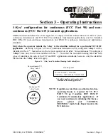
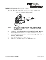
1. Insert correct color-coded ‘i-Key’
.
This coded electronic key sets the unique operating
parameters for a given control system. In the PS
AT
family of controllers, these parameters
include, address code, operating frequency and function key (pushbutton) configurations,
whereas in the PS
EZ
and PS
CS
families of controllers the
‘i-key’
only defines and enables the
pushbutton operating functions for a specific PRC system. The ‘
i-key
’ is simply installed by
pressing into its receptacle and may be further secured to the controller using the metal stud
located behind the rubber bumper. Note that a Pendant Station Controller will not operate
without an
‘i-Key’
installed.
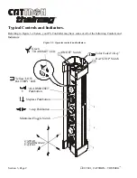
2. Set red STOP Switch to ‘RUN’
. Pulling this switch upward enables power to be applied to the
PS controller. If the switch has been pushed down to the ‘STOP’ position, you will first have to
unlatch the switch knob by rotating in a clockwise direction.
3. Set Power ON/OFF Switch to ‘ON’
.
Rotating this switch clockwise applies power to the PS
controller. Two quick ‘beeps’ with the green TRANSMIT LED flashing rhythmically indicates
the controller is ready for use and a power up message has been sent to the target
receiver/decoder. The targeted receiver/decoder will respond by energizing the mainline
contactor of your controlled equipment.
Содержание i-Key
Страница 2: ......
Страница 14: ...Page xii 01 2001 CATTRON THEIMEG TM EZ CS AT Rx Rx Tx Tx Tx Rx Rx Rx ...
Страница 20: ...Section 1 Page 6 01 2001 CATTRON THEIMEG TM This page intentionally left blank ...
Страница 44: ...Section 4 Page 4 01 2001 CATTRON THEIMEG TM ...
Страница 52: ...Section 4 Page 12 01 2001 CATTRON THEIMEG TM This page intentionally left blank ...
Страница 68: ...Section 5 Page 16 01 2001 CATTRON THEIMEG TM This page intentionally left blank ...
Страница 75: ... 01 2001 CATTRON THEIMEG TM Section 6 Page 7 Item 7 Carrying strap shoulder Part 42C 0057 ...
Страница 89: ......

