background image

 
Maintenance, Errors, Repair 

REFLECTA/5


Page D6 

Mounting & Operations Manual 

5-Years-Spare-Parts-Outfit 
A box containing the most essential spare parts is availale as an extra (Order No. 10651).  
Included are: 
1.  One cover glass/bottom glass  
2.  Two rubber gaskets 
3.  Two filling screw gaskets 
4.  Two pivots for the directional system assembly 
5. Two jewels 
6.  Three each bulbs for illumination 
7.  One centre pivot for azimuth device (only bearing compass) 
8.  One reflection mirror 
 
Required Tools 
Special tools are not required. 

• 

Slot screw driver, 3 mm, to unscrew the pivot from the float, 

• 

Box wrench, 5.5 mm, or pointed pliers for counter nut of the pivot 

• 

Slot screw driver, 7 mm, for the cover rings of the compass 

• 

Slot screw driver, 12 mm, for the filling screw of the compass 

• 

Pipe wrench for removal of external gimbal trunnions 

• 

Screw spanner, 17 mm, for the internal gimbal trunnions 

 
Replacement of Directional System (Card Assembly) or Pivot and Jewel 
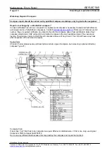
1.  Place the compass on a horizontal plane and solid surface. 
2.  Remove the divided verge ring by unscrewing the relevant screws (only bearing/reflector compass). The 

“180“ mark is in ahead direction. 

3.  Remove the upper cover ring by unscrewing the relevant screws. Mark the orientation before. 
4.  Remove rubber gasket and cover glass. Mark the orientation of the cover glass before. Take the cover glass 

with the centre pivot or use a small screw driver and lift up the glass at its edge. 

5.  Remove the directional system by hand and replace by a new one if necessary. 
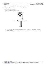
6.  Remove pivot. Loosen the pivot counter nut from below of the float by use of the box wrench 5.5 mm or 

pointed pliers. Now the pivot can be unscrewed from above with the screw driver of 3 mm. Replace with a 
new pivot (recommended each time the compass is opened or latest at routine service). 

7.  Replace the jewel: Unscrew the jewel retainer by hand or with pliers. Now take the jewel and replace by a 

new one. 

8.  Close the compass with the cover glass. Watch its orientation. The cover glass should be centric to the 

compass bowl. Check this visually. Insert the rubber gasket and fasten the upper cover ring. Tighten the 
screws with as equal as possible force around the whole circle. 

9.  Fit the divided verge ring (if any). Place the azimuth device on the compass for adjustment. Adjust the 

divided verge ring to match the lubber marks.Turn the azimuth device to all four major directions and adjust 
the divided ring to be centric to the centre pivot. 

10. Fill up the compass fluid. Refer to paragraph: “Filling the compass“. 
 
Replacement of Upper Cover Glass 
1.  Place the compass on a horizontal, plane and solid surface. 
2.  Only bearing/reflector compass: Remove the divided verge ring by unscrewing the relevant screws. The 

“180“ mark is in ahead direction. 

3.  Remove the upper cover ring by unscrewing the relevant screws. Mark the orientation before. 
4.  Remove rubber gasket. Take the cover glass at the centre pivot or use a small screw driver and lift up the 

glass at its edge. 

5.  Replace the old cover glass with a new one. 
6.  The cover glass should be centric to the compass bowl. Check this visually. Insert the rubber gasket and 

fasten the upper cover ring. Tighten the screws with as equal as possible force around the whole circle. 

7.  Only bearing/reflector compass. Fit the divided verge ring. Place the azimuth device on the compass for 

adjustment. Adjust the divided verge ring to match the lubber marks.Turn the azimuth device to all four major 
directions and adjust the divided ring to be centric to the centre pivot. 

8.  Complete the compass fluid. Refer to paragraph: “Filling the compass“. 

Alterations / Errors reserved 
Cassens & Plath GmbH, Am Lunedeich 131, 27572 Bremerhaven, Germany, Tel. +49 471 483 999 0, Fax +49 471 483 999 10 

www.cassens-plath.de

, [email protected]


Содержание Reflecta/5

Страница 1: ... Device REFLECTA 5 Operation Installation Cassens Plath GmbH Manufacturers of Nautical Equipment Am Lunedeich 131 D 27572 Bremerhaven Germany Tel 49 471 483 999 0 Fax 49 471 483 999 10 sales cassens plath de www cassens plath de ...

Страница 2: ...ions D1 Compass Routine Service D1 Replacing Bulbs D1 Cleaning of Reflector Optics D2 Errors Diagnosis and Help Visible Compass Errors D3 Indication Errors D3 Replacement of compass D3 Workshop Repair of Compass D5 Installation Procedure Outline E1 Range of Delivery E1 Location of Binnacle Magnetic Requirements E2 Location of Binnacle Constructional Requirements E3 Optical Arrangement Reflection T...

Страница 3: ... and remove 6 Compass 2 Binnacle Base 7 Fixing flange of reflection tube 3 Compass bridge 8 Knurled knob for reflection mirror 4 Reflection tube 9 Reflection mirror 5 Mirror head with aperture 10 Foundation Alterations Errors reserved Cassens Plath GmbH Am Lunedeich 131 27572 Bremerhaven Germany Tel 49 471 483 999 0 Fax 49 471 483 999 10 www cassens plath de sales cassens plath de ...

Страница 4: ...uirements for magnetic compasses are laid down in ISO 25862 2009 E as well as in the relevant national documents REFLECTA 5 fullfills all these regulations for costal navigation Technical Data Compass Binnacle Card height 210 600 mm Total height 510 900 mm Maximum width measured over D cylinders 800 mm Weight of binnacle and compass complete net 30 kg Material of binnacle column seawater resistant...

Страница 5: ... Reflection tube Reflection tube with mirror head and mounting flange rubber gasket Accessories as option Instruction are included separately as required Approvals Type 21 compass is type approved by German BSH and European MED for coastal use MED European Community BSH 4612 4011402 09 Certificates of Lloyds Register of Shipping LRS German Lloyd GL Amercian Bureau of Shipping ABS can be supplied o...

Страница 6: ... the reflection mirror 030 040 050 060 030 040 050 060 Short optical way large image Long optical way small image Adjustment of Mirror Head Reflection tube Mirror head Take the rotary knobs here by hand to turn and swivel reflection mirror Reflection mirror White mirror for daylight use black mirror for night use Maintenance Clean reflection mirrors with a weak not scratching cloth The axles of th...

Страница 7: ...ate bearing use the slit of the ocular sight vane Compass bearing azimuth of land marks up tp 30 of elevation Read the compass card as illustrated below Relative bearing of land marks up to 30 of elevation Read the graduated verge ring of the compass at the index of the ocular sight vane The scale ring is marked all round If semi circuar bearings are required subtract 360 from the all round value ...

Страница 8: ... fore and aft will be visible These are covered by safety plates to fix the compass in its position Loosen the screws of the safety plates and remove the compass If a detector is fitted watch the cables Unfit the detector cables either by removing the connector or by unscrewing the wires in a junction box Dont remove the detector itself from the compass because this destroys the alignment When rei...

Страница 9: ...e magnets are stored within one of the magazines This corrector arrangement adjusts about 35 of deviation if compass and magazines are mounted as directed Unscrew the side covers to make out the drillings to insert the magnets For B adjustment install one each magazine at port and starboard of the compass as to be seen from the following drawing 1 The magnets have to be exact parallel to ship s lo...

Страница 10: ...adjust the induced weak magnetic field caused by the magnetic iron hull or superstructure of the vessel It can neutralize 6 of deviation heading error The correction by μ metal induction sheets works on needle induction and will vary with magnetic latitude Therefore it is intended only for limited voyage in coastal navigation on fishing vessels or tugs The D corrector arrangement consists of a cen...

Страница 11: ...the position in the deviation diary For D correction the cylinders has to be approached or drawn away from the binnacle column D Bracket Binnacle Column D Cylinder Bolt to fix the sphere Adjustment Heeling Correction 12800 Extra First Install reflection tube as describted in this handbook Reflection tube Reflexions Rohr Binnacle column Standsäule Voraus Ahead Heeling Corrector On compass axis K Ko...

Страница 12: ...agnet below Schraube Lösen zur Entnahme des Magneten von unten Slit to arrest the chain Schlitz zur Arretierung der Kette Numbered adjusting chain Nummerierte Justierkette Magnet tube with chain removed Magnethülse an Kette entnommen Heeling magnet Turn to turn the field direction K Magnet Drehen für Feldumkehr Unscrew cover to turn the magnet Deckel abschrauben zum Drehen des Magnet Alterations E...

Страница 13: ...egulations it should be installed in the ship s centre line where the influence does not occur If it is necessary to move the compass binnacle to port or starboard then the iron free zone has to be moved correspondingly to reduce the deflection Alterations Errors reserved Cassens Plath GmbH Am Lunedeich 131 27572 Bremerhaven Germany Tel 49 471 483 999 0 Fax 49 471 483 999 10 www cassens plath de s...

Страница 14: ... correct function will be certified by the BSH authorized compass work shop by the official BSH test certificate If the compass service was carried out by a foreign and not BSH authorized work shop because the vessel has not called a German port the certificate issued can be sent to the BSH for acceptance A preliminary functional test with oboard means is described below in chapter Friction Error ...

Страница 15: ...Manual Cleaning of Reflection Optics Use only a soft and non scatching cloth Lens Position Alterations Errors reserved Cassens Plath GmbH Am Lunedeich 131 27572 Bremerhaven Germany Tel 49 471 483 999 0 Fax 49 471 483 999 10 www cassens plath de sales cassens plath de ...

Страница 16: ...pare compass or order replacement compass see below and hand over to a qualified servce workshop as soon as possible Indication Errors Static Indication Errors Indication errors can be discovered by comparison of magnetic compass and gyro compass indication Magnetic and gyro compass indicate different types of heading Magnetic and true So when compare both apply variation and deviation correction ...

Страница 17: ...l away the deflecting magnet Watch how the card returns to the undeflected direction A tolerance of less 0 5 is acceptable after stabilizing 4 Deflect the compass card as mentioned above to the opposite direction by 2 and repeat the settling process Again the compass card must return to the original direction within a tolerance of 0 5 5 Repeat these tests each 45 of compass orientation 6 If the co...

Страница 18: ...ll send a refurbished compass to the next available stopp of the vessel and invoice The ship may return to C P the old compass and we will buy it back The ship will have a pay back after inspection of the returned compass Spare Parts In case of order please quote part description and also type of compass here steering optional reflector compass Type 21 Compass Fluid If less then 5 cm3 fluid has to...

Страница 19: ...tine service 7 Replace the jewel Unscrew the jewel retainer by hand or with pliers Now take the jewel and replace by a new one 8 Close the compass with the cover glass Watch its orientation The cover glass should be centric to the compass bowl Check this visually Insert the rubber gasket and fasten the upper cover ring Tighten the screws with as equal as possible force around the whole circle 9 Fi...

Страница 20: ...hat the filling screw is upside Unscrew the filling screw with screw driver of 12 mm and complete fluid In case larger quantities are needed use only original compass fluid 39012 Smaller quantities up to 5 cm3 can be completed with Ethanol or distilled water Medical syrings are suitable to complete the fluid 2 Close the compass with the filling screw Use a new gasket 3 To ensure the tightness of t...

Страница 21: ...talling compass Column 6 Connecting illumination 7 Carrying out functional tests and preparing compass adjustment Range of Delivery Compass Binnacle Reflector reading device Column with mounting bolts washers gaskets hood magnetic steeing compass optional bearing compass Separate Correctors as extras only B C corrector magazine 18100 consisting of 3 magazines with 4 bar magnets 100 mm long x 10 mm...

Страница 22: ...nterfering fields 1 The distance to magnetic iron measured as spherical radius around the compass depends on the overall length of the vessel The following diagram will give an impression of the necessary distances according to IMO A 382 X regulations This is relevant also for wheelhouse front wall boards including their mounting systems pipes installed below the compass bridge plating cable wirew...

Страница 23: ...nnacle Constructional Requirements 1 The magnetic compass should be installed on the ship s centreline otherwise asymmetric iron around will cause non adjustable errors If a place on the centre line is not possible then the iron free zone has to be moved with the compass to port or starboard Authority has to be contacted for approval 2 The compass foundation should be designed to reduce vibrations...

Страница 24: ...which ever way clearances in the binnacle base allow the water to flow out again Therfore please do not seal the binnacle base against the compass deck 5 The vertical axles of reflection tube and binnacle column have to be parallel to ensure line up of optical components and to grant a symmetric reflection image 6 If a higher foundation is necessary to reach a suitable iron safe distance of the ma...

Страница 25: ...n cables and detector cable should be furnished with a sleeve app 30 mm internal Ø for bending protection Binnacle column Cable lead in protection tube inner dia 30 mm Reflection tube 4x Fixing bolts included 12 mm 80 mm long Foundation Deck min 450 mm 130 400 440 75 75 8x45 Outer binnacle base shape Hole circle diameter of fixing bolts 8 x fixing bolts for reflection tube yard supply Cut out of r...

Страница 26: ...lection tube must be installed before installation of compass binnacle gasket flange 130 125 168 8xM6 126 168 208 Bolts flange yard supply deck Alterations Errors reserved Cassens Plath GmbH Am Lunedeich 131 27572 Bremerhaven Germany Tel 49 471 483 999 0 Fax 49 471 483 999 10 www cassens plath de sales cassens plath de ...

Страница 27: ...Cut tube from above 4 CUTUBE only Lift flange and use clamp screws amagnetic yard supply to fix CUTUBE and FIXTUBE Fix the flange by amagnetic screws to the deck Seal gap flange tube and flange deck from above with mastics 5 Hide cut edge of ceiling with ring yard supply Foundation min 70 mm Deck Ceiling 1 2 3 4 5 Alterations Errors reserved Cassens Plath GmbH Am Lunedeich 131 27572 Bremerhaven Ge...

Страница 28: ...nto the wheelhouse Move the column to its final position an fix it Make sure the cable does not obscure the optical channel 3 Install a junction box yard supply inside the wheelhouse near to the cable lead in Wiring refer to chapter Wiring Note Do not seal the the binnacle base on the platform Water inside the binnacle column should flow off this way Binnacle base Fixing bolt M12x80 Foundation Dec...

Страница 29: ...crew socket Illumination Dimmer Extra Optionally available are dimmers with or without enclosure for 220 240 VAC 115 VAC or 24 VDC According to international regulations the compass illumination should be of adjustable brightness Install the dimmer near to the helmsman s position The dimmers are of rheostat type Instructions are attached to the dimmers if ordered Caution Wires inside enclosure are...

Страница 30: ...se Hot Dimmers 4 7 kOhm for 230 VAC 1 8 kOhm for 115 VAC 680 Ohm for 24 VDC alternative Cables about 80 cm below binnacle base Junction box yard supply Alterations Errors reserved Cassens Plath GmbH Am Lunedeich 131 27572 Bremerhaven Germany Tel 49 471 483 999 0 Fax 49 471 483 999 10 www cassens plath de sales cassens plath de ...

Страница 31: ...ection Optics Use only a soft and non scatching cloth a a Lens inside of the binnacle colum Accessible by removing the compass ref to chapter Compass Binnacle Outline Alterations Errors reserved Cassens Plath GmbH Am Lunedeich 131 27572 Bremerhaven Germany Tel 49 471 483 999 0 Fax 49 471 483 999 10 www cassens plath de sales cassens plath de ...

Страница 32: ...sses the picture may be much smaller than the reflection mirror 030 040 050 060 030 040 050 060 Short optical way large picture Long optical way small picture 5 Can the mirror head and reflection mirror be turned Are white and black mirror of the reflection mirror undamaged 6 Make sure that the B C correctors are available for compass adjustment At delivery B C magnets are located in their magazin...

Отзывы: