background image

LK-120

JUL. 2010

LK-120

Ver. 2 : Jan. 2012

ELECTRONIC KEYBOARD

Содержание LK-120

Страница 1: ...LK 120 JUL 2010 LK 120 Ver 2 Jan 2012 ELECTRONIC KEYBOARD...

Страница 2: ...S SPECIFICATIONS 1 BLOCK AND WIRING DIAGRAM 2 PCB INFORMATION 3 CIRCUIT DESCRIPTION 4 PRINTED CIRCUIT BOARDS 5 DISASSEMBLY 7 DIAGNOSTIC PROGRAM 16 EXPLODED VIEW 22 PARTS LIST 23 SCHEMATIC DIAGRAMS 26...

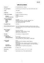
Страница 3: ...chord name fingering timing indicator key lighting voice fingering Other Functions Transpose F to C to F half note Tuning Adjustable A4 Approx 440 Hz 50 cents Initial value A4 Approx 440 Hz Speakers 1...

Страница 4: ...in CN201 17 pin CN205 CN206 CN207 CN6 CN8 CN204 LSP LSP CN9 CN7 CN4 CN5 RSP RSP CN803 16 pin CN801 13 pin CN802 13 pin CN1 16 pin CN2 16 pin CN506 16 pin CN503 12 pin CN504 6 pin CN504 6 pin CN505 6 p...

Страница 5: ...eyboard LED Controller Reset IC Buttons Right Speaker Terminal Power Amp PCB PCB ASSY PSA1 MX820 PSA1 Power Supply Circuit Power Ampli er Power Switch Volume Buttons DC 9 5 V Jack Left Speaker Termina...

Страница 6: ...5 B5 KI6 C6 C6 D6 D6 E6 F6 F6 G6 KI7 G6 A6 A6 B6 C7 NOMENCLATURE OF KEYS C2 C3 C4 C5 C6 C7 BUTTON MATRIX KO8S KO9S KO10S KO11S KI0S 0 5 TONE STEP 1 KI1S 1 6 RHYTHM STEP 2 KI2S 2 7 SONG BANK STEP 3 KI3...

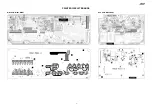
Страница 7: ...LK 120 5 PRINTED CIRCUIT BOARDS Main PCB M821 MDA1 Sub PCB M820 PSA1...

Страница 8: ...LK 120 6 Keyboard PCB M800 KYA1 Keyboard LED PCB M821 LDA1 Keyboard LED PCB M821 LDA1 Keyboard PCB M800 KYA2...

Страница 9: ...or blanket before starting disassembling There are several kinds of screws Be sure to use the correct type of screws when z z reassembling It is advisable to sort the screws as shown below after remov...

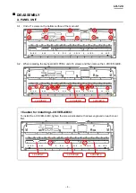
Страница 10: ...AAA When replacing the keyboard LED PCBs undo 16 screws and then remove the L COVER A B C AAAAA L COVER C L COVER B L COVER A Caution for installing L COVER A B C To install the L COVER A B C tighten...

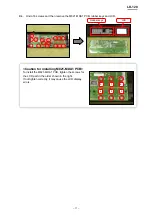
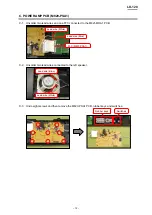
Страница 11: ...Turn over the panel unit AAAAA Unsolder two battery lead wires AAAAA Unsolder two FFCs AAAAA Lead wire Red Lead wire Black FFC M800 KYA2 FFC M821 LDA2 Remove the panel unit AAAAA M821 MDA1 PCB M820 P...

Страница 12: ...Unsolder two FFCs BBBBB FFC M800 KYA2 FFC M821 LDA2 Unsolder two lead wires and one FFC BBBBB Lead wire White Lead wire Blue FFC M820 PSA1 Unsolder two lead wires connected to the right speaker BBBBB...

Страница 13: ...PCB rubber keys and LCD BBBBB Rubber keys LCD Caution for installing M821 MDA1 PCB To install the M821 MDA1 PCB tighten the screws for the LCD part in the order shown in the right If not tighten corr...

Страница 14: ...onnected to the M821 MDA1 PCB CCCCC Lead wire White Lead wire Blue FFC M820 PSA1 Unsolder two lead wires connected to the left speaker CCCCC Lead wire Blue Lead wire White Undo eight screws and then r...

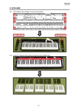
Страница 15: ...LK 120 13 KEYBOARD DDD Undo eight screws and then remove the side panels DDDDD Left side panel Right side panel Undo 21 screws and then remove the white keys and black keys DDDDD...

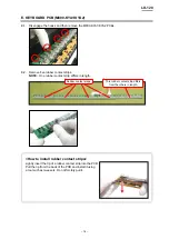
Страница 16: ...EEEE One rubber contact strip differs in length NNNNNN Rubber contact strips This rubber contact strip differs from the others in length How to install rubber contact strips Lightly insert the tip of...

Страница 17: ...s FFFFF Turn over the M821 LDA1 LDA2 PCBs FFFFF Do not touch the LEDs NNNNNN Unsolder three FFCs and then remove the M821 LDA1 LDA2 PCBs FFFFF After repairing arrange the FFCs again NNNNNN Undo 12 scr...

Страница 18: ...NNNN Release the 0 and START STOP buttons After the diagnostic program is launched the test menu appears TEST ITEMS Pushing a test button enables the corresponding test item to be tested Test Items Bu...

Страница 19: ...LK 120 17 DIAGNOSTIC PROGRAM MODE SWITCH CHECK AAA Switch the mode switch and check that the following screen appears on the LCD AAAAA Mode Switch LCD FINGERED CASIO CHORD NORMAL...

Страница 20: ...y or a button is pressed in a wrong order The error tone sounds and the button number and NG appear on the LCD You cannot cancel this check procedure mid way NNNNNN 01 02 05 06 10 11 12 13 24 25 26 03...

Страница 21: ...in the order indicated in the illustration below There should be no key of which LED brightness is too bright or too faint 1 2 3 4 5 6 7 8 9 10 11 12 13 14 15 16 17 18 19 LCD CHECK EEE Press the STEP...

Страница 22: ...irmation chords in the order indicated in the illustration below AUTO POWER OFF CHECK FFF Press the PART SELECT button to perform the Auto Power Off Check FFFFF The power supply is turned off and no s...

Страница 23: ...s twice The stroke and the load of keys are normal The difference in height and the gap between keys are even Press the keys in the order shown in the illustration below NNNNNN HEADPHONES CHECK HHH Pe...

Страница 24: ...LK 120 22 EXPLODED VIEW 17 33 30 31 18 28 27 26 25 24 22 21 20 23 19 29 2 32 34 35 37 44 45 46 47 38 39 43 43 40 42 41 38 36 6 8 9 10 7 11 12 14 16 4 48 3 13 1 30 15 5 5...

Страница 25: ...he latest Parts Price Code at PARTS FINDER on the Casio Service WEB site https www servicecasio com 3 As for spare parts order and supply refer to the GUIDEBOOK for Spare parts Supply published separa...

Страница 26: ...1 1 X D203 D204 10261170 DIODE SRT14 A2 2 2 2 2 X D206 D207 79114195 DIODE UDZSTE 175 6B 2 2 2 2 X D201 D202 10371167 DIODE L1SS355T1G 2 2 2 2 X Q204 10206676 TRANSISTOR KTC2026 Y U P 1 1 1 1 X Q201 6...

Страница 27: ...KER C10J01A 2 2 2 2 X N 31 10366691 PANEL RJM510265 003V01 1 1 1 1 X 32 10366841 SIDE PANEL LEFT RJM510267 001V01 1 1 1 1 X 33 10366842 SIDE PANEL RIGHT RJM510268 001V01 1 1 1 1 X Main case unit 34 10...

Страница 28: ...LK 120 26 SCHEMATIC DIAGRAMS Main PCB M821 MDA1 to KYA2 CN803 to LDA2 CN506 to PSA1 CN206 to PSA1 CN207 RIGHT SPEAKER to RIGHT SPEAKER to PSA1CN201 Not used...

Страница 29: ...120 27 Sub PCB M820 PSA1 to BATTERY to LEFT SPEAKER to KYA2 CN803 to MDA1 CN3 POWER MODE SWITCH SW201 VOLUME SW202 LEFT SPEAKER BATTERY DC 9 V IN J201 PHONES OUTPUT J202 to MDA1 CN7 to MDA1 CN6 Not us...

Страница 30: ...LK 120 28 Keyboard LED PCB M821 LDA1 to LDA2 CN503 to LD3M JG...

Страница 31: ...LK 120 29 Keyboard LED PCB M821 LDA2 to MDA1 CN2 to LD5M JE to LD4M JF to LDA1 CN501...

Страница 32: ...LK 120 30 Keyboard LED PCB CSM446 LD3M LD4M LD5M to LDA1 CN502 to LDA2 CN504 to LDA2 CN505...

Страница 33: ...LK 120 31 Keyboard PCB M800 KYA1 KYA2 to KYA2 CN802 to KYA1 CN801 to MDA1 CN1 Not used Not used...

Страница 34: ...Overseas Service Division 6 2 Hon machi 1 Chome Shibuya ku Tokyo 151 8543 Japan Ver 1 Dec 2011 Correction of the PARTS LIST P24 Ver 2 Jan 2012 Correction of the EXPLODED VIEW P22 Correction of the PA...

Отзывы: