INTRODUCTION
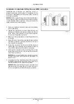
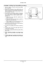
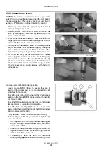
Installation of flange connectors
Flange connections typically have four bolts, although
some flange connections may have more or fewer. The
flange connector consists of four main components:
• A body (flange head)
• An O-ring
• One “captive” or two “split” flange clamps
• Bolts and washers
1.
Remove protective connector caps only immediately
prior to assembly.
2.
Inspect the components to ensure that the male and
female port threads and sealing surfaces are free of
burrs, nicks, and scratches, or any foreign material.
Do not use if impurities are found.
3.
Place the O-ring in the groove, the groove will be
either on the port side or the flange side.
4.
Assemble the flange head and the clamps.
5.
Position and hold the flange assembly over the port.
6.
Finger tighten the bolt hardware evenly and in a
crossing pattern.
7.
Tighten the bolt hardware to
60%
of the torque value.
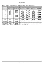
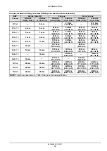
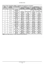
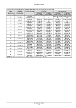
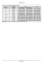
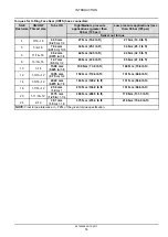
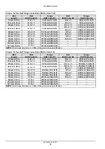
Use the same crossing pattern. See the torque tables
for the proper torque value.
NOTE:
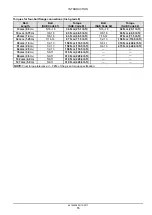
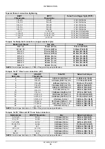
For bolt hardware that is not Metric Class 8.8
and 10.9 or Inch Grade 8 see the “Torque - Minimum
tightening torques for normal assembly”
Minimum tightening torques for normal assembly
()
.
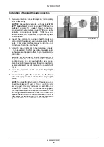
8.
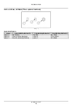
Tighten the bolt hardware 1 and 2 to
100%
of the
torque value.
9.
Tighten the bolt hardware 3 and 4 to
100%
of the
torque value.
RAIL15TLB0611BA
4
48194558 20/10/2017
60

