


52
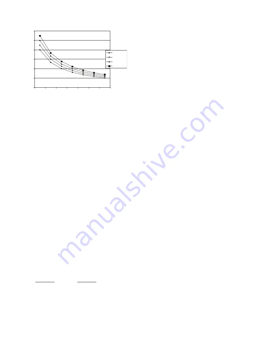
Fig. 69 — CO
2
Sensor Maximum Range Settings
EXHAUST SETPOINT ADJUSTMENT
The exhaust setpoint will determine when the exhaust fan runs
based on damper position (if accessory power exhaust is in-
stalled). The setpoint is modified with the Exhaust Fan Set-
point (EXH SET) potentiometer. See Fig. 64. The setpoint rep-
resents the damper position above which the exhaust fans will
be turned on. When there is a call for exhaust, the EconoMi$er
IV controller provides a 45 ± 15 second delay before exhaust
fan activation to allow the dampers to open. This delay allows
the damper to reach the appropriate position to avoid unneces-
sary fan overload.
MINIMUM POSITION CONTROL
There is a minimum damper position potentiometer on the
EconoMi$er IV controller. See Fig. 64. The minimum damper
position maintains the minimum airflow into the building
during the occupied period.
When using demand ventilation, the minimum damper position
represents the minimum ventilation position for Volatile Or-
ganic Compound (VOC) ventilation requirements. The maxi-
mum demand ventilation position is used for fully occupied
ventilation.
When demand ventilation control is not being used, the mini-
mum position potentiometer should be used to set the occupied
ventilation position. The maximum demand ventilation posi-
tion should be turned fully clockwise.
Adjust the minimum position potentiometer to allow the mini-
mum amount of outdoor air, as required by local codes, to enter
the building. Make minimum position adjustments with at least
10°F temperature difference between the outdoor and return-
air temperatures.
To determine the minimum position setting, perform the fol-
lowing procedure:
1. Calculate the appropriate mixed air temperature using the
following formula:
T
O
= Outdoor-Air Temperature
OA = Percent of Outdoor Air
T
R
= Return-Air Temperature
RA = Percent of Return Air
T
M
= Mixed-Air Temperature
As an example, if local codes require 10% outdoor air during
occupied conditions, outdoor-air temperature is 60°F, and re-
turn-air temperature is 75°F.
(60 x 0.10) + (75 x 0.90) = 73.5°F
2. Disconnect the supply air sensor from terminals T and T1.
3. Ensure that the factory-installed jumper is in place across
terminals P and P1. If remote damper positioning is being
used, make sure that the terminals are wired according to
Fig. 43 and that the minimum position potentiometer is
turned fully clockwise.
4. Connect 24 vac across terminals TR and TR1.
5. Carefully adjust the minimum position potentiometer until
the measured mixed air temperature matches the calcu-
lated value.
6. Reconnect the supply air sensor to terminals T and T1.
Remote control of the EconoMi$er IV damper is desirable
when requiring additional temporary ventilation. If a field-sup-
plied remote potentiometer (Honeywell part number
S963B1128) is wired to the EconoMi$er IV controller, the
minimum position of the damper can be controlled from a re-
mote location.
To control the minimum damper position remotely, remove the
factory-installed jumper on the P and P1 terminals on the
EconoMi$er IV controller. Wire the field-supplied potentiome-
ter to the P and P1 terminals on the EconoMi$er IV controller.
(See Fig. 67.)
DAMPER MOVEMENT
Damper movement from full open to full closed (or vice versa)
takes 2
1
/
2
minutes.
THERMOSTATS
The EconoMi$er IV control works with conventional thermo-
stats that have a Y1 (cool stage 1), Y2 (cool stage 2), W1 (heat
stage 1), W2 (heat stage 2), and G (fan). The EconoMi$er IV
control does not support space temperature sensors. Connec-
tions are made at the thermostat terminal connection board lo-
cated in the main control box.
OCCUPANCY CONTROL
The factory default configuration for the EconoMi$er IV con-
trol is occupied mode. Occupied status is provided by the black
jumper from terminal TR to terminal N. When unoccupied
mode is desired, install a field-supplied timeclock function in
place of the jumper between TR and N. When the timeclock
contacts are closed, the EconoMi$er IV control will be in occu-
pied mode. When the timeclock contacts are open (removing
the 24-v signal from terminal N), the EconoMi$er IV will be in
unoccupied mode.
DEMAND CONTROLLED VENTILATION (DCV)
When using the EconoMi$er IV for demand controlled ventila-
tion, there are some equipment selection criteria which should
be considered. When selecting the heat capacity and cool ca-
pacity of the equipment, the maximum ventilation rate must be
evaluated for design conditions. The maximum damper posi-
tion must be calculated to provide the desired fresh air.
Typically the maximum ventilation rate will be about 5 to 10%
more than the typical cfm required per person, using normal
outside air design criteria.
A proportional anticipatory strategy should be taken with the
following conditions: a zone with a large area, varied occupan-
cy, and equipment that cannot exceed the required ventilation
rate at design conditions. Exceeding the required ventilation
rate means the equipment can condition air at a maximum ven-
tilation rate that is greater than the required ventilation rate for
maximum occupancy. A proportional-anticipatory strategy will
cause the fresh air supplied to increase as the room CO
2
level
increases even though the CO
2
setpoint has not been reached.
By the time the CO
2
level reaches the setpoint, the damper will
be at maximum ventilation and should maintain the setpoint.
In order to have the CO
2
sensor control the EconoMi$er damp-
er in this manner, first determine the damper voltage output for
(T
O
x
OA
)
+ (T
R
x
RA
)
= T
M
100
100
0
1000
2000
3
000
4000
5000
6000
2
3
4
5
6
7
8
RANGE
C
ONFIGURA
TION
(ppm)
CO
S
EN
S
OR MAX RANGE
S
ETTING
2
8
00 ppm
900 ppm
1000 ppm
1100 ppm
Содержание WeatherMaster Puron 48HC D17
Страница 18: ...18 COOLING CHARGING CHARTS Fig 22 Cooling Charging Chart 15 Ton ...
Страница 19: ...19 Fig 23 Cooling Charging Chart 17 5 Ton ...
Страница 20: ...20 Fig 24 Cooling Charging Chart 20 Ton ...
Страница 21: ...21 Fig 25 Cooling Charging Chart 25 Ton ...
Страница 37: ...37 Fig 48 Unit Control Box IGC Location IGC Board IGC Board Side view Front view ...
Страница 40: ...40 Fig 51 Typical IGC Wiring Diagram ...
Страница 46: ...46 Fig 57 RTU Open Overlay for Economizer Wiring ...
Страница 47: ...47 Fig 58 VFD Overlay for W2770 Controller Wiring ...
Страница 84: ...84 Fig B 48HC D17 D28 Control Diagram 208 230 3 60 460 575 3 60 ...
Страница 85: ...85 Fig C 48HC D17 D28 Power Diagram 208 230 3 60 ...
Страница 86: ...86 Fig D 48HC D17 D28 Power Diagram 460 3 60 ...
Страница 87: ...87 Fig E 48HC D17 D28 Power Diagram 575 3 60 ...
Страница 88: ...88 Fig F 48HC D17 D28 Control Diagram with Humidi MiZer System ...
Страница 89: ...89 Fig G 48HC D17 D28 Power Diagram 208 230 3 60 with Humidi MiZer System ...
Страница 90: ...90 Fig H 48HC D17 D28 Power Diagram 460 3 60 with Humidi MiZer System ...
Страница 91: ...91 Fig I 48HC D17 D28 Power Diagram 575 3 60 with Humidi MiZer System ...
Страница 92: ...92 Fig J PremierLink System Control Wiring Diagram 50HE500891 F ...
Страница 93: ...93 Fig K PremierLink System Control Wiring Diagram with Humidi MiZer System ...
Страница 94: ...94 Fig L RTU OPEN Wiring Diagram ...
Страница 95: ...95 Fig M RTU OPEN Wiring Diagram with Humidi MiZer System ...
Страница 97: ......