1-25
CAUTION
Anytime power cable is connected to module and
the refrigeration unit is not operating, the
battery will be discharging.
Therefore, the
power cable must be unplugged from module
except when performing cold treatment
recording, calibration, or charging battery.
NOTE
Stow power cable in dummy receptacle and
insert dummy plug in module receptacle to
prevent corrosion of terminals when not in use.
b. Battery Check and Charging
Plug power cable into module and start unit or apply
24 vac to module. If low battery charge light illuminates,
charge battery by operating unit or applying 24 vac to
module until charge light extinguishes. Alternatively,
install a module with a pre-charged battery. (When
charging from an external source, apply 24 vac to pin PL2.
Ground pin PL1.)
NOTE
Normally, charging the battery until the light is
extinguished will provide adequate power to
perform cold treatment calibration without AC
power available to unit. Depending on the
ambient temperature and degree of discharge,
charging for as little as one hour or as much as 24
hours could be required to extinguish the light.
Charging for 4 to 6 hours after light is
extinguished is required to fully charge battery.
1.15 USDA COLD TREATMENT PROCEDURE
Sustained cold temperature has been employed as an
effective postharvest method for the control of the
Mediterranean and certain other tropical fruit flies.
Exposing infested fruit to temperatures of 2.2 degrees
Celsius (36
_
F) or below for specific periods results in the
mortality of the various stages of this group of notoriously
injurious insects.
In response to the demand to replace fumigation
with this enviromentally sound process, Carrier has
integrated this Cold Treatment capability into its
microprocessor controller. These units have the ability to
maintain the container temperature within 1/4 degree
Celsius of setpoint and record minute changes in product
temperature within the DataCORDER memory and
thus meet USDA criteria (refer to section 1.13.7).
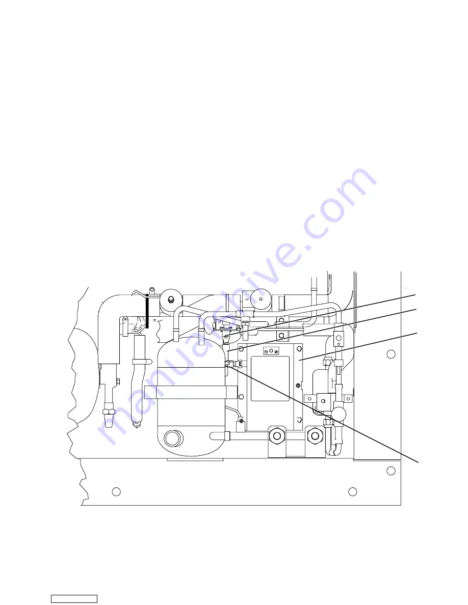
3
1
2
4
1. Dummy Receptacle
2. Power Cable
3. 12v DC Battery and Charger Module
or 9 “C”Size Battery Box
4. Dummy Plug
Figure 1-8. USDA Battery Module
Downloaded from
Содержание TRANSICOLD 69NT20-274
Страница 2: ...Downloaded from ManualsNet com search engine ...
Страница 4: ...Downloaded from ManualsNet com search engine ...
Страница 100: ...5 28 Figure 5 14 Electrical Wiring Diagram Model 69NT20 274 1 Sheet 1 of 2 Downloaded from ManualsNet com search engine ...
Страница 101: ...5 29 Figure 5 14 Electrical Wiring Diagram Model 69NT20 274 1 Sheet 2 of 2 Downloaded from ManualsNet com search engine ...
Страница 104: ...5 32 Figure 5 16 Electrical Wiring Diagram Model 69NT40 444 6 Sheet 1 of 2 Downloaded from ManualsNet com search engine ...
Страница 105: ...5 33 Figure 5 16 Electrical Wiring Diagram Model 69NT40 444 6 Sheet 2 of 2 Downloaded from ManualsNet com search engine ...
Страница 108: ...5 36 Figure 5 18 Electrical Wiring Diagram Model 69NT40 454 1 Sheet 1 of 2 Downloaded from ManualsNet com search engine ...
Страница 109: ...5 37 Figure 5 18 Electrical Wiring Diagram Model 69NT40 454 1 Sheet 2 of 2 Downloaded from ManualsNet com search engine ...
Страница 112: ...5 40 Figure 5 20 Electrical Wiring Diagram Model 69NT40 444 9 Sheet 1 of 2 Downloaded from ManualsNet com search engine ...
Страница 113: ...5 41 Figure 5 20 Electrical Wiring Diagram Model 69NT40 444 9 Sheet 2 of 2 Downloaded from ManualsNet com search engine ...
Страница 136: ...5 64 Figure 5 32 Electrical Wiring Diagram Model 69NT20 274 2 Sheet 1 of 2 Downloaded from ManualsNet com search engine ...
Страница 137: ...5 65 Figure 5 32 Electrical Wiring Diagram Model 69NT20 274 2 Sheet 2 of 2 Downloaded from ManualsNet com search engine ...
Страница 182: ...Downloaded from ManualsNet com search engine ...


