


REFRIGERATOR
REFRIGERATOR
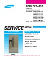
PRODUCT FEATURE
For the latest information, Please access to our service web site (http://itself.sec.samsung.co.kr)
●
●
NEW DIGITAL DISPLAY(LED)
●
●
TOWER LIGHTING
●
●
CONTOUR DOOR/HIDDEN HINGE
●
●
CLEAN LOOK DRAWER
●
●
TWIN COOLING
●
●
HUMAN TOUCH HANDLE
SIDE BY SIDE
BASIC : RS265BBWP, RS267LBBP
MODEL NAME : RS263BBWP RS265LBBP
RS263BBBB RS265LBWP
RS263BBSH RS267LBSH
RS264ABBP RS264ABRS
RS264ABSH RS264ABWP
RS267BBBB RS269LBRS
RS267BBSH RS267BBRS
MODEL CODE : RS263/264/265/267/269**/XAA
06년 A-TOP(LOWE'S)-080115
2008.1.15 11:48 AM
페이지1
RS26**
Summary of Contents for RS265BBWP
Page 18: ...18 Refrigerator 2 PRODUCT SPECIFICATIONS 2 9 Cooling Air Circulation Freezer...
Page 68: ...7 EXPLODED VIEW PARTS LIST 7 3 Cabinet 7 1 69...
Page 78: ...79 8 BLOCK DIAGRAM...
Page 79: ...80 9 WIRING DIAGRAM 9 1 RS265BB RS267BB RS267LB RS269LB...
Page 80: ...81 9 WIRING DIAGRAM 9 2 RS263BB RS265LB...
Page 82: ...83 10 PCB DIAGRAM 10 2 CONNECTOR ARRANGEMENT Main Board...
Page 83: ...84 11 CIRCUIT DIAGRAM...


