4-13
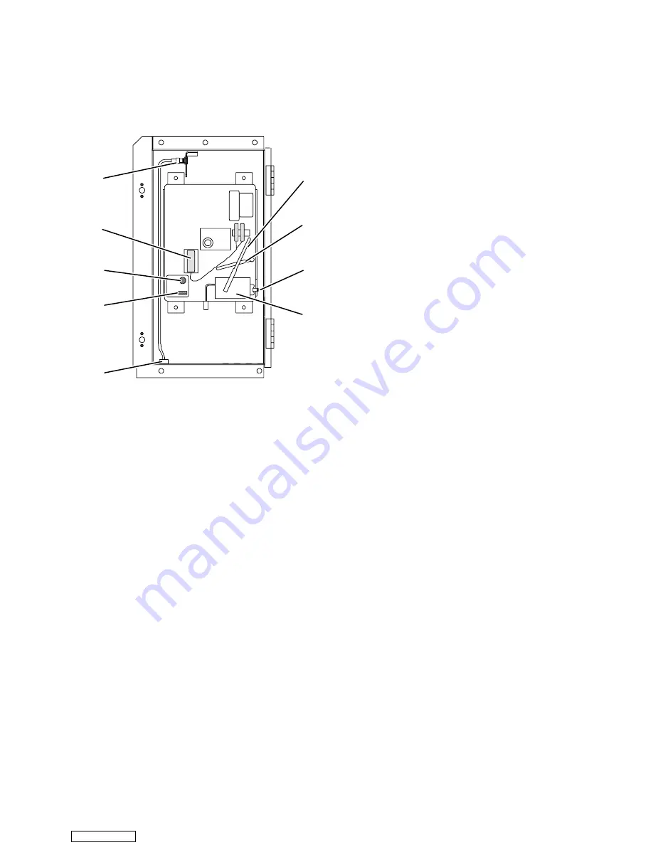
c. Replacing Sensor Probe
1. Remove box from unit.
2. Remove nut and bushing, item 9, Figure 4-17.
3. Install replacement probe and bushing. Seal with
silicone before securing to case.
4. Install box into unit.
1. Voltage Indicator
2. Indicator Test Switch
3. Battery (“C” size, Alkaline)
4. Sensor Assembly
5. Stylus
6. Stylus Lifter
7. Setscrew (Adjustment)
8. Bulb and Mechanism
9. Bushing and Nut
1
2
3
4
9
5
6
7
8
Figure 4-17. Saginomiya Recording Thermometer
4.20 RUST PREVENTION AND MAINTENANCE OF
PAINTED SURFACES
a. Rust Prevention --- Components
To prevent corrosion, external parts such as
compressor, cable clamps, fasteners, and evaporator fan
motor, should be sprayed with clear urethane (CRC
Chemicals, Part No. 2-53) every six months. The inside of
the control panel should be sprayed (CRC Chemicals,
Part No. 3-36) at similar time periods.
b. Maintenance of Painted Surfaces
The refrigeration unit is protected by a special paint
system against the corrosive atmosphere in which it
normally operates. However, should the paint system be
damaged, the base metal can corrode. In order to protect
the refrigeration unit from the highly corrosive sea
atmosphere or if the protective paint system is scratched
or damaged, clean area to bare metal using a wire brush,
emery
paper
or
equivalent
cleaning
method.
Immediately following cleaning, spray or brush on zinc
rich primer. After the primer has dried, spray or brush on
finish coat of paint to match original unit color.
4.21 SERVICING THE WATER-COOLED
CONDENSER
NOTE
When Oakite compound No. 32 is being used for
the first time, the local Oakite Technical Service
representative should be called in for their
suggestions in planning the procedure. They will
show you how to do the work with a minimum
dismantling of equipment: how to estimate the
time and amount of compound required; how to
prepare the solution; how to control and
conclude the de-scaling operation by rinsing and
neutralizing equipment before putting it back
into service. Their knowledge of metals, types of
scale,
water
conditions
and
de-scaling
techniques will be invaluable to you.
The water-cooled condenser is of the shell and coil
type with circulating water through the cupro-nickel coil.
The refrigerant vapor is admitted to the shell side and is
condensed on the outer surface of the coil.
Rust, scale and slime on the water-cooling surfaces
inside of the coil interfere with the transfer of heat,
reduce system capacity, cause higher head pressures and
increase the load on the system.
By checking the leaving water temperature and the
actual condensing temperature, it can be determined if
the condenser coil is becoming dirty. A larger than
normal difference between leaving condensing water
temperature and actual condensing temperature,
coupled with a small difference in temperature of
entering and leaving condensing water, is an indication of
a dirty condensing coil.
To find the approximate condensing temperature,
with the unit running in the cooling mode, install a gauge
0 to 36.2 kg/cm
@
(0 to 500 psig) on the compressor
discharge service valve.
For example: if the discharge pressure is 10.3 kg/cm
@
(147 psig), and referring to Table 4-6, R-12
pressure-temperature chart, the 10.3 kg/cm
@
(147 psig)
converts to 46
_
C (115
_
F).
If the water-cooled condenser is dirty, it may be
cleaned and de-scaled by the following procedure:
a. Turn unit off and disconnect main power.
b. Disconnect water pressure switch tubing by
loosening the two flare nuts. Install 1/4 inch flare cap on
water-cooled condenser inlet tube (replaces tubing flare
nut). De-scale tubing if necessary.
What You Will Need:
1. Oakite composition No. 22, available as a powder in
68 kg (150 lb) and 136 kg (300 lb).
2. Oakite composition No. 32, available as a liquid in
cases, each containing 3.785 liters (4 U.S. gallon) bottles
and also in carboys of 52.6 kg (116 lbs) net.
3. Fresh clean water.
Downloaded from
Содержание TRANSICOLD 69NT20-274
Страница 2: ...Downloaded from ManualsNet com search engine ...
Страница 4: ...Downloaded from ManualsNet com search engine ...
Страница 100: ...5 28 Figure 5 14 Electrical Wiring Diagram Model 69NT20 274 1 Sheet 1 of 2 Downloaded from ManualsNet com search engine ...
Страница 101: ...5 29 Figure 5 14 Electrical Wiring Diagram Model 69NT20 274 1 Sheet 2 of 2 Downloaded from ManualsNet com search engine ...
Страница 104: ...5 32 Figure 5 16 Electrical Wiring Diagram Model 69NT40 444 6 Sheet 1 of 2 Downloaded from ManualsNet com search engine ...
Страница 105: ...5 33 Figure 5 16 Electrical Wiring Diagram Model 69NT40 444 6 Sheet 2 of 2 Downloaded from ManualsNet com search engine ...
Страница 108: ...5 36 Figure 5 18 Electrical Wiring Diagram Model 69NT40 454 1 Sheet 1 of 2 Downloaded from ManualsNet com search engine ...
Страница 109: ...5 37 Figure 5 18 Electrical Wiring Diagram Model 69NT40 454 1 Sheet 2 of 2 Downloaded from ManualsNet com search engine ...
Страница 112: ...5 40 Figure 5 20 Electrical Wiring Diagram Model 69NT40 444 9 Sheet 1 of 2 Downloaded from ManualsNet com search engine ...
Страница 113: ...5 41 Figure 5 20 Electrical Wiring Diagram Model 69NT40 444 9 Sheet 2 of 2 Downloaded from ManualsNet com search engine ...
Страница 136: ...5 64 Figure 5 32 Electrical Wiring Diagram Model 69NT20 274 2 Sheet 1 of 2 Downloaded from ManualsNet com search engine ...
Страница 137: ...5 65 Figure 5 32 Electrical Wiring Diagram Model 69NT20 274 2 Sheet 2 of 2 Downloaded from ManualsNet com search engine ...
Страница 182: ...Downloaded from ManualsNet com search engine ...


