T-354
7–12
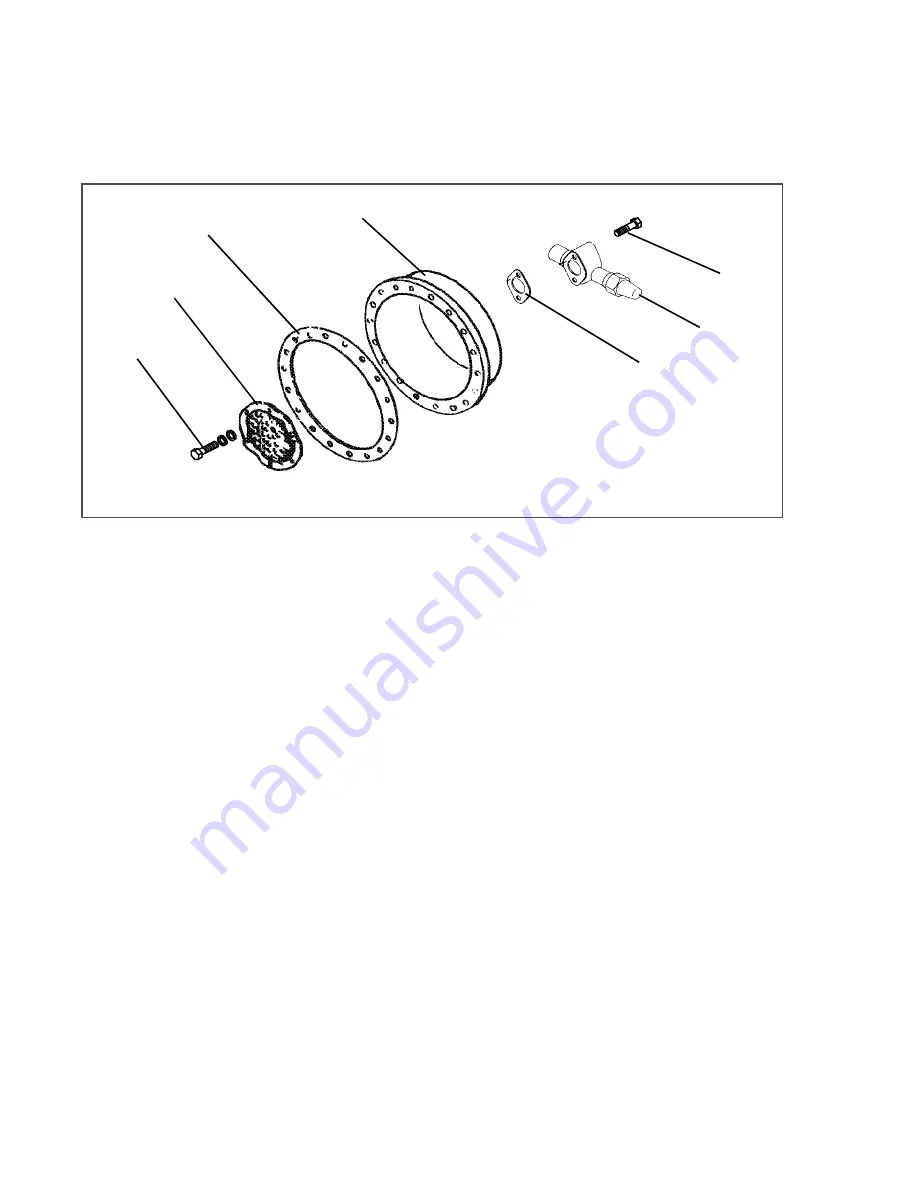
1. Be very careful not to damage the motor windings when removing the motor end cover (see
as the cover fits over the winding coils. Loosen the cap screws, break the seal, and then re move all cap
screws except one in the top of the cover. While holding the cover in place, remove the remaining cap
screw. Do not allow the cover to drop from its own weight. To prevent striking the winding, remove the cover
horizontally and in line with the motor axis.
Figure 7.11 Motor End Cover
1. Strainer Screws and Washers
2. Suction Strainer
3. Motor End Cover Gasket
4. Motor End Cover
5. Valve Gasket
6. Suction Service Valve
7. Valve Cap screw
- - - - -
2. Remove the refrigerant suction strainer. If it is removed with ease, it may be cleaned with solvent and
replaced. If the strainer is broken, corroded or clogged with dirt that is not easily removed, replace the
strainer. Install new gaskets upon reassembly.
3. Block the compressor crankshaft so that it cannot turn. Use a screwdriver to bend back the tabs on the lock-
washer, and remove the equalizer tube and lock screw assembly (see
). The slingers at the end
of the tube draw vapor from the crankcase. Remove the rotor using a jack bolt. Insert a brass plug into the
rotor hole to prevent damage to the end of the crankshaft.
4. If the piston rings extend beyond the cylinder tops, the pistons can be pulled through the bottom plate open-
ing after the piston rings are compressed. A piston ring compressor will facilitate removal. Each piston pin is
locked in place by lock rings, which are snapped into grooves in the piston wall (see
5. Since the stator cannot be replaced in the field, the terminal plate assembly need not be disturbed unless a
leak exists and the plate assembly needs to be re placed. If no terminal plate repair is required, proceed with
reassembly.
Содержание 69NT40-541-306
Страница 2: ......
Страница 4: ......
Страница 10: ......
Страница 14: ......
Страница 78: ...T 354 5 8 Figure 5 3 Controller Operation Perishable Mode Figure 5 4 Controller Operation Frozen Mode ...
Страница 142: ...T 354 8 2 Figure 8 2 Schematic Diagram Standard Unit Configuration BASED ON 62 66686 00 ...
Страница 143: ...8 3 T 354 Figure 8 3 Unit Wiring Diagram Standard Unit Configuration 1 of 2 BASED ON 62 66686 00 ...
Страница 144: ...T 354 8 4 Figure 8 4 Unit Wiring Diagram Standard Unit Configuration 2 of 2 BASED ON 62 66686 00 ...
Страница 148: ...T 354 8 8 ...
Страница 152: ......
Страница 153: ......


