background image

6. a. Press INCREASE or DECREASE to change the

time values. Override values are in one-hour incre-
ments, up to 4 hours.

b. Press ENABLE to select days in the day-of-week

fields. Press DISABLE to eliminate days from the
period.

7. Press ENTER to register the values and to move

horizontally (left to right) within a period.

8. Press EXIT to leave the period or override.

9. Either return to Step 4 to select another period or

override, or press

EXIT

again to leave the cur-

rent time schedule screen and save the changes.

10. Holiday Designation (HOLIDEF table) may be found in

the Service Operation section, page 42. You must assign
the month, day, and duration for the holiday. The Broad-
cast function in the BRODEF table also must be en-
abled for holiday periods to function.

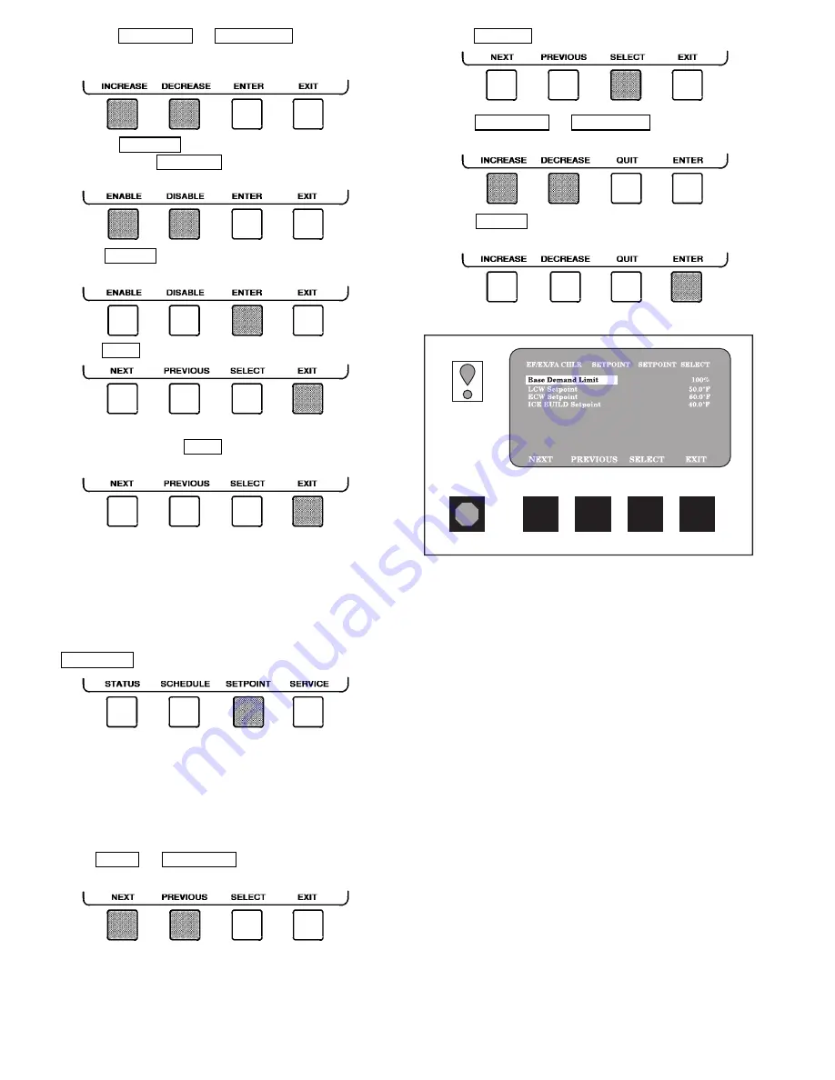
TO VIEW AND CHANGE SET POINTS (Fig. 17)
1. To view the Set Point table, at the Menu screen press

SETPOINT .

2. There are 4 set points on this screen: Base Demand Limit;

LCW Set Point (leaving chilled water set point); ECW
Set Point (entering chilled water set point); and ICE BUILD
set point. Only one of the chilled water set points can be
active at one time, and the type of set point is activated
in the Service menu. ICE BUILD is also activated and
configured in the Service menu.

3. Press NEXT or PREVIOUS to highlight the desired

set point entry.

4. Press SELECT to modify the highlighted set point.

5. Press INCREASE or DECREASE to change the se-

lected set point value.

6. Press ENTER to save the changes and return to the

previous screen.

SERVICE OPERATION — To view the menu-driven pro-
grams available for Service Operation, see the Service Op-
eration section, page 42. For examples of LID display screens,
see Table 2.

LEGEND FOR TABLE 2 — LID DISPLAY DATA

CCN

— Carrier Comfort Network

CHWR — Chilled Water Return
CHWS — Chilled Water Supply
Compr — Compressor
Dec

— Decrease

Ecw

— Entering Chilled Water

HGBP

— Hot Gas Bypass

Inc

— Increase

LCW

— Leaving Chilled Water

mA

— Milliamps

P

— Pressure

PIC

— Product Integrated Controls

Refrig

— Refrigerant

T

— Temperature

Temp

— Temperature

Fig. 17 — Example of Set Point Screen

22

Содержание 17EX Series

Страница 1: ...use only warm 110 F 43 C water DO NOT REUSE disposable nonreturnable cylinders or attempt to refill them It is DANGEROUS AND ILLEGAL When cylinder is emptied evacuate remaining gas pressure loosen the collar and unscrew and discard the valve stem DO NOT INCINERATE CHECK THE REFRIGERANT TYPE before adding refrigerant to the chiller The introduction of the wrong refrigerant can cause dam age or malf...

Страница 2: ...reeze 33 Auxiliary Compressor Oil Pump Control 33 Auxiliary Gear Oil Pump Control 33 Shaft Seal Oil Control 33 Ramp Loading Control 33 Capacity Override 35 High Discharge Temperature Control 35 Oil Sump Temperature Control 35 Oil Cooler 36 Remote Start Stop Controls 36 Spare Safety Inputs 36 Spare Alarm Contacts 36 Condenser Pump Control 36 Condenser Freeze Prevention 36 Tower Fan Relay 36 Auto Re...

Страница 3: ... CHILLER CYCLES MAINTENANCE SAFETY DEVICES AND PROCEDURES CHECK OPERATOR KNOWLEDGE THIS MANUAL OPERATING INSTRUCTIONS 62 63 Operator Duties 62 Page Prepare the Chiller for Start Up 62 Starting the Chiller 62 Check the Running System 62 Stopping the Chiller 62 After Limited Shutdown 63 Extended Shutdown 63 After Extended Shutdown 63 Cold Weather Operation 63 Manual Guide Vane Operation 63 Refrigera...

Страница 4: ...king the Display Messages 84 Checking Temperature Sensors 84 RESISTANCE CHECK VOLTAGE DROP CHECK SENSOR ACCURACY DUAL TEMPERATURE SENSORS Page Checking Pressure Transducers 84 OIL DIFFERENTIAL PRESSURE POWER SUPPLY MODULE CALIBRATION TROUBLESHOOTING TRANSDUCERS TRANSDUCER REPLACEMENT Control Algorithms Checkout Procedure 85 Control Test 85 Control Modules 96 RED LEDs GREEN LEDs Notes on Module Ope...

Страница 5: ...7EX CHILLER FAMILIARIZATION Chiller Identification Label Fig 1 The iden tification label is located on the right side of the chiller con trol center panel The label contains information on model number refrigerant charge rated voltage etc System Components Fig 2 The components include the cooler and condenser heat exchangers in sepa rate vessels compressor compressor and gear lubrication pack ages...

Страница 6: ...oler size can be combined with any available condenser size NOTE For details on motor size designations see below ASME U STAMP ARI Air Conditioning and Refrigeration Institute PERFORMANCE CERTIFIED 60 Hz Only Fig 1 Model Number Identification 6 ...

Страница 7: ...Filter 18 Refrigerant Charging Service Valve 19 Refrigerant Liquid Line to Cooler 20 Power Panel 21 Oil Level Sight Glasses 2 22 Oil Drain and Charging Valve 23 Oil Heater Hidden 24 Compressor Oil Pump 25 Compressor Oil Cooler Filter 26 Local Interface Display Control Panel 27 Cooler Relief Valves Behind Compressor Hidden 28 Economizer Storage Vessel 29 Economizer Storage Vessel Relief Valves 30 P...

Страница 8: ...mperature is outside the operating temperature range of 150 to 160 F 66 to 71 C External Gear Oil Cooling The external gear oil is also water cooled Water flow through the gear oil cooler is manually adjusted by a plug valve to maintain an oper ating temperature of approximately 130 F 54 C If so equipped an oil heater in the reservoir helps to maintain the oil tem perature under cold ambient opera...

Страница 9: ...temperature of approximately 130 F 54 C Upon leaving the cooler section Item 13 of the oil cooler filter the oil is filtered Item 11 and is directed to the pres sure control valve Item 7 Before entering the pressure control valve the oil pressure Item 16 and temperature Item 8 are monitored by the PIC A portion of the oil then lubricates the gear bearings Item 2 Another portion is directed through...

Страница 10: ...TO POWER PANEL OIL THERMISTOR OIL HEATER DRAIN CHARGING VALVE COMPRESSOR OIL SUCTION PRESSURE PUMP SEAL OIL RETURN OIL CHARGING ELBOW THRUST BEARING COAST DOWN RESERVOIRS SHAFT SEAL 13 12 PLUG VALVE TO PIC CONTROLLER MAIN OIL RESERVOIR OIL FILTER OIL COOLER FILTER 17 16 11 10 7 9 6 3 4 2 SEAL END BEARING 1 5 15 14 8 Fig 4 17EX Compressor Lubrication Cycle 10 ...

Страница 11: ...er The microprocessor control system matches the cool ing capacity of the chiller to the cooling load while provid ing state of the art chiller protection The system controls cooling load within the set point plus the deadband by sens ing the leaving chilled water or brine temperature and regu lating the inlet guide vane via a mechanically linked actua tor motor The guide vane is a variable flow p...

Страница 12: ...ring 24 v or less power panel 115 v control voltage up to 600 v for oil pump power starter cabinet chiller power wiring per job requirement Table 1 Major PIC Components and Panel Locations PIC COMPONENT PANEL LOCATION Processor Sensor Input Output Module PSIO Control Center Starter Management Module SMM Starter Cabinet Local Interface Device LID Control Center 6 Pack Relay Board Control Center 8 I...

Страница 13: ...nsor 17 Oil Pump Conduit 18 Oil Pump Sensor 19 PIC Control Panel 20 Condenser Leaving Water Temperature Sensor 21 Gear Oil Cooler Solenoid Conduit 22 Cooler Temperature Cable 23 Cooler Leaving Water Temperature Sensor 24 Cooler Entering Water Temperature Sensor 25 Cooler Pressure Sensor 26 Refrigerant Charging Valve LEGEND Fig 6 17EX Controls and Sensor Locations cont 13 ...

Страница 14: ...t Integrated Controls PSIO Processor Sensor Input Output Module 1 Optional 8 Input Module for Spare Inputs to Control Interface One of Two Available 2 PSIO 3 LID Input Output Interface Panel Display 4 Oil Differential Pressure Power Supply Module Hidden 5 LID Light Hidden 6 6 Pack Relay Board 7 Circuit Breakers 4 Fig 9 Control Center Front View Shown with Options Module 14 ...

Страница 15: ...LEGEND EQUIP GND Equipment Ground GRD Ground M Motor TEWAC Totally Enclosed Water to Air Cooled Fig 10 17EX Chiller Power Panel and Controls Connections 15 ...

Страница 16: ... PUMP CONTACTOR 5C These contactors are lo cated in the power panel They operate all 200 to 575 v oil pumps The PIC energizes the contactor to turn on the oil pumps as necessary HOT GAS BYPASS CONTACTOR RELAY 3C Optional This relay located in the power panel con trols the opening of the hot gas bypass valve The PIC en ergizes the relay during low load high lift conditions OIL AUXILIARY RELAY 4C Th...

Страница 17: ...hin any menu structure use the SELECT softkey to choose the desired table or item The softkey modification choices displayed will de pend on whether the selected item is a discrete point ana log point or an override point Press the softkey that cor responds to your configuration selection or press the QUIT softkey If the QUIT softkey is depressed the configuration will not be modified Use the foll...

Страница 18: ... the desired point 2 Press SELECT to access the highlighted point 3 Press RELEASE to remove the override and return the point to the PIC s automatic control Override Indication An override value is indicated by SUPVSR SERVC or BEST flashing next to the point value on the Status table TO VIEW OR CHANGE TIME SCHEDULE OPERATION Fig 14 1 On the Menu screen press SCHEDULE 2 Press NEXT or PREVIOUS to hi...

Страница 19: ...T ENTER NEXT PREVIOUS SELECT EXIT Select the Setpoint ALARM HISTORY CONTROL TEST CONTROL ALGORITHM STATUS EQUIPMENT CONFIGURATION EQUIPMENT SERVICE TIME AND DATE ATTACH TO NETWORK DEVICE LOG OUT OF DEVICE CONTROLLER IDENTIFICATION LID CONFIGURATION NEXT PREVIOUS SELECT EXIT SEE FIGURE 16 Select a Service Table STATUS STATUS STATUS STATUS 01 02 03 04 EXIT SELECT PREVIOUS NEXT Select a Schedule 1 2 ...

Страница 20: ...4 Lead Lag Status WSMDEFME Water System Manager Control Status OCCDEFM Time Schedule Status EQUIPMENT CONFIGURATION List the Equipment Configuration Tables CONFIG LEAD LAG OCCDEFCS HOLIDEF BRODEF WSMALMDF ALARMDEF CONS_DEF RUNT_DEF Select a Parameter NEXT PREVIOUS SELECT EXIT Modify a Parameter ENTER ENABLE DISABLE QUIT DECREASE INCREASE ENTER QUIT QUIT YES NO ENTER NEXT PREVIOUS SELECT EXIT Selec...

Страница 21: ...ID to another CCN network or device Attach to LOCAL to enter this machine To upload new tables Default Screen MENU RESET CCN LOCAL LOG OUT OF DEVICE EXIT INCREASE DECREASE ENTER CONTROLLER IDENTIFICATION PSIO Controller Identification Table To modify PSIO CCN Address To View PSIO Software Version last 2 digits on part number indicate software version LID CONFIGURATION List Network Devices Local De...

Страница 22: ... LCW Set Point leaving chilled water set point ECW Set Point entering chilled water set point and ICE BUILD set point Only one of the chilled water set points can be active at one time and the type of set point is activated in the Service menu ICE BUILD is also activated and configured in the Service menu 3 Press NEXT or PREVIOUS to highlight the desired set point entry 4 Press SELECT to modify th...

Страница 23: ...The asterisk or exclamation point indicates that the value on that line has exceeded or is approaching a limit For more information on alarms and alerts see the Alarms and Alerts sec tion page 16 EXAMPLE 1 STATUS01 DISPLAY SCREEN To access this display from the LID default screen 1 Press MENU 2 Press STATUS STATUS01 will be highlighted 3 Press SELECT DESCRIPTION RANGE UNITS REFERENCE POINT NAME AL...

Страница 24: ...erator from the LID screen or from another control device such as a Carrier Comfort Network CCN terminal EXAMPLE 3 STATUS03 DISPLAY SCREEN To access this display from the LID default screen 1 Press MENU 2 Press STATUS 3 Scroll down to highlight STATUS03 4 Press SELECT DESCRIPTION RANGE UNITS REFERENCE POINT NAME ALARM HISTORY OPTIONS BOARD 1 Demand Limit 4 20 mA 4 20 mA DEM OPT Temp Reset 4 20 mA ...

Страница 25: ...PMP2 Gear Oil Pressure 6 7 to 420 46 to 2896 psi kPa GEAROILP Gear Oil Temperature 40 to 245 40 to 118 DEG F DEG C GEAROILT EXAMPLE 5 SETPOINT DISPLAY SCREEN To access this display from the LID default screen 1 Press MENU 2 Press SETPOINT DESCRIPTION CONFIGURABLE RANGE UNITS REFERENCE POINT NAME DEFAULT VALUE Base Demand Limit 40 100 DLM 100 LCW Setpoint 20 120 6 7 48 9 DEG F DEG C lcw sp 50 0 10 ...

Страница 26: ... 15 0 8 DEG F DEG C restd 2 0D 0D Degrees Reset 30 30 17 17 DEG F DEG C deg chw 5D 3D Select Enable Reset Type 0 3 res sel 0 ECW CONTROL OPTION DISABLE ENABLE ecw opt DISABLE Demand Limit At 20 mA 40 100 dem 20ma 40 20 mA Demand Limit Option DISABLE ENABLE dem sel DISABLE Auto Restart Option DISABLE ENABLE astart DISABLE Remote Contacts Option DISABLE ENABLE r contact DISABLE Temp Pulldown Deg Min...

Страница 27: ...LE RANGE UNITS REFERENCE POINT NAME DEFAULT VALUE LEAD LAG SELECT DISABLE 0 LEAD 1 LAG 2 STANDBY 3 0 3 leadlag 0 Load Balance Option DISABLE ENABLE loadbal DISABLE Common Sensor Option DISABLE ENABLE commsens DISABLE LAG Percent Capacity 25 75 lag per 50 LAG Address 1 236 lag add 92 LAG START Timer 2 60 MIN lagstart 10 LAG STOP Timer 2 60 MIN lagstop 10 PRESTART FAULT Timer 0 30 MIN preflt 5 STAND...

Страница 28: ... 1 Surge HGBP Delta T1 0 5 15 0 3 8 3 DEG F DEG C hgb dt1 1 5 0 8 Surge HGBP Delta P1 30 170 207 1172 PSI kPa hgb dp1 50 345 Min Load Points T1 P1 Surge HGBP Delta T2 0 5 15 0 3 8 3 DEG F DEG C hgb dt2 10 5 6 Surge HGBP Delta P2 30 170 207 1172 PSI kPa hgb dp2 85 586 Full Load Points T2 P2 Surge HGBP Deadband 1 3 0 6 1 6 DEG F DEG C hgb dp 1 0 6 Surge Delta Percent Amps 10 50 surge a 25 Surge Time...

Страница 29: ...ow Alarm Temp Alert Threshold Spare Temp 4 Enable 0 4 spr4 en 0 Spare Temp 4 Alert 40 245 40 118 DEG F DEG C spr4 al 245 118 Spare Temp 5 Enable 0 4 spr5 en 0 Spare Temp 5 Alert 40 245 40 118 DEG F DEG C spr5 al 245 118 Spare Temp 6 Enable 0 4 spr6 en 0 Spare Temp 6 Alert 40 245 40 118 DEG F DEG C spr6 al 245 118 Spare Temp 7 Enable 0 4 spr7 en 0 Spare Temp 7 Alert 40 245 40 118 DEG F DEG C spr7 a...

Страница 30: ...des show the associated point in alert Reference point names with capital letters can be read by CCN and Building Supervisor software EXAMPLE 12 MAINTENANCE MAINT02 DISPLAY SCREEN To access this display from the LID default screen 1 Press MENU 2 Press SERVICE 3 Scroll down to highlight CONTROL ALGORITHM STATUS 4 Press SELECT 5 Scroll down to highlight MAINT02 6 Press SELECT DESCRIPTION RANGE STATU...

Страница 31: ...down to highlight MAINT04 6 Press SELECT DESCRIPTION RANGE STATUS UNITS REFERENCE POINT NAME LEAD LAG Configuration DISABLE LEAD LAG STANDBY INVALID leadlag Current Mode DISABLE LEAD LAG STANDBY CONFIG llmode Load Balance Option DISABLE ENABLE loadbal LAG Start Time 0 60 MIN lagstart LAG Stop Time 0 60 MIN lagstop Prestart Fault Time 0 30 MIN preflt Pulldown Delta T Min x xx D DEG F D DEG C pull d...

Страница 32: ...ed on the LID from a set ting of 2 to 10 and the default setting is 6 0 Increasing ei ther of these settings causes the vanes to respond more slowly than at a lower setting The PROPORTIONAL ECW GAIN can be adjusted at the LID display from a setting of 1 0 to 3 0 with a default setting of 2 0 Increase this setting to increase guide vane response to a change in entering chilled water temperature DEM...

Страница 33: ...reen freezes to allow the operator to see the condition of the chiller at the time of the alarm Knowledge of the operating state of the chiller at the time an alarm occurs is useful when troubleshooting Cur rent chiller information can be viewed on the STATUS screens see Table 2 Examples 1 4 Once all existing alarms are cleared by pressing the RESET softkey the default LID screen returns to normal...

Страница 34: ... or 85 for 3 seconds SINGLE CYCLE 50 for one cycle COMPRESSOR MOTOR LOAD Compressor Amps 110 for 30 seconds Preset 10 with compressor running Preset 10 with compressor off Preset STARTER ACCELERATION TIME Determined by inrush current going below 100 compressor motor load 45 seconds For chillers with reduced voltage mechanical and solid state starters 10 seconds For chillers with full voltage start...

Страница 35: ...re to the evapora tor refrigerant temperature If the difference between these 2 temperatures is 50 F 27 8 C or less the start up is delayed until the oil temperature difference is 50 F 27 8 C or more Once this temperature is confirmed the start up continues The oil heater relay is energized whenever the chiller com pressor is off and the oil sump temperature is less than 150 F 65 6 C or the oil su...

Страница 36: ...reeze Prevention This control al gorithm helps prevent condenser tube freeze up by energiz ing the condenser pump relay If the pump is controlled by the PIC starting the pump helps prevent the water in the condenser from freezing Condenser freeze prevention can occur whenever the chiller is not running except when it is either actively in pumpdown or in pumpdown lockout with the freeze prevention ...

Страница 37: ...ence Enter the difference in chilled water temperature at which the full amount of reset occurs CHW DELTA T FULL RESET Next enter the amount of reset DEGREES RESET Reset Type 3 can now be activated Demand Limit Control Option Requires Optional 8 Input Module The demand limit may be externally controlled with a 4 to 20 mA signal from an Energy Management System EMS The option 20 mA DE MAND LIMIT OP...

Страница 38: ...of lead chiller load balancing if configured staggered restart of the chillers after a power failure chillers may be piped in parallel or in series chilled water flow COMMON POINT SENSOR INSTALLATION Lead lag operation does not require a common chilled water point sensor Common point sensors can be added to the 8 input option module if desired Refer to the certified drawings for termination of sen...

Страница 39: ... a start re quest This timer s function is to provide a time out if there is a pre start alert condition that prevents the chiller from starting in a timely manner If the lag chiller does not achieve start up before the pre start fault time elapses then the lag chiller is stopped and the standby chiller is requested to start if configured and ready Standby Chiller Configuration and Operation The c...

Страница 40: ...ice build time schedule defines the periods during which the ice build option can be activated if the ice build option is enabled If the ice build time schedule overlaps other sched ules the ice build time schedule takes priority During an ice build period the WATER BRINE CONTROL POINT is set to the ICE BUILD SETPOINT SETPOINT screen for tem perature control The ICE BUILD RECYCLE OPTION and ICE BU...

Страница 41: ... CCN device if the chiller has been connected to a CCN network This may include other PIC controlled chillers uploads changes from a new PSIO or LID module or up graded software Figure 20 shows the ATTACH TO NETWORK DEVICE table as it appears on the LID The LOCAL entry is always the PSIO module address of the chiller the LID is mounted on Whenever the controller identification of the PSIO is chang...

Страница 42: ...e last key is pressed the default screen displays the LID screen light goes out analogous to a screen saver and the LID logs out of the password protected SERVICE menu Other screens and menus such as the STATUS screen can be accessed without the password by pressing the appropri ate softkeys HOLIDAY SCHEDULING Fig 21 The time schedules may be configured for special operation during holiday pe riod...

Страница 43: ...fter flow is verified the chilled water brine temperature is compared to WATER BRINE CON TROL POINT plus DEADBAND If the temperature is less than or equal to this value the PIC turns off the condenser pump relay and goes into a RECYCLE mode If the water brine temperature is high enough the start up sequence continues and checks the guide vane position If the guide vanes are more than 6 open the st...

Страница 44: ... parameter value to the percent of amps at which the motor will shut down The default setting is 100 amps no soft stop When the automatic soft stop amps threshold is being ap plied a status message SHUTDOWN IN PROGRESS COM PRESSOR UNLOADING displays Chilled Water Recycle Mode When the compres sor is running under light load conditions the chiller may cycle off and wait until the load increases to ...

Страница 45: ... and the factory mounted starter MOTOR The motor may be provided with a shipping brace or shipping bolt normally painted yellow to prevent shaft movement during transit It must be removed prior to operation See Fig 24 The motor should be inspected for any temporary yellow caution tags with legends that convey information concern ing actions necessary before the motor can be safely oper ated Any sl...

Страница 46: ...r is spring isolated keep all springs blocked in both directions in order to prevent possible piping stress and damage during the transfer of refrigerant from vessel to ves sel during the leak test process or any time refrigerant is trans ferred Adjust the springs when the refrigerant is in operat ing condition and when the water circuits are full Refrigerant Tracer Carrier recommends using an en ...

Страница 47: ...Fig 25 17EX Leak Test Procedures 47 ...

Страница 48: ...16 55 138 222 76 140 229 09 Table 5B HFC 134a Pressure Temperature C TEMPERATURE C PRESSURE kPa 18 0 44 8 16 7 51 9 15 6 59 3 14 4 66 6 13 3 74 4 12 2 82 5 11 1 90 8 10 0 99 4 8 9 108 0 7 8 118 0 6 7 127 0 5 6 137 0 4 4 147 0 3 3 158 0 2 2 169 0 1 1 180 0 0 0 192 0 1 1 204 0 2 2 216 0 3 3 229 0 4 4 242 0 5 0 248 0 5 6 255 0 6 1 261 0 6 7 269 0 7 2 276 0 7 8 284 0 8 3 290 0 8 9 298 0 9 4 305 0 10 0...

Страница 49: ... tracer Raise the vessel pres sure in increments until the leak is detected If refrig erant is used the maximum gas pressure is approximately 70 psig 483 kPa at normal ambient temperature 5 Repair the leak retest and proceed with dehydration Chiller Dehydration Dehydration is recommended if the chiller has been open for a considerable period of time if the chiller is known to contain moisture or i...

Страница 50: ...ssor and gear oil pumps power panel and pumpout unit 6 Check that all electrical equipment and controls are prop erly grounded in accordance with job drawings certi fied drawings and all applicable electrical codes 7 Make sure that the customer s contractor has verified the proper operation of the pumps cooling tower fans and associated auxiliary equipment This includes en suring that motors are p...

Страница 51: ...hat may have occurred in transit Refer to Table 6 for recommended bolt torques Table 6 Recommended Motor Fastener Tightening Torques Bolt size 1 4 5 16 3 8 1 2 5 8 3 4 7 8 1 11 3 11 2 Grade SAE GR 5 Torque Ft lbs 3 5 7 12 31 63 115 180 275 550 960 N m 4 7 9 5 16 42 85 156 244 373 746 1302 Bolt size M4 M6 M8 M10 M12 M10 M12 M16 Grade DIN 8 8 DIN 12 9 Torque Ft lbs 2 8 15 35 65 45 92 225 N m 2 7 11 ...

Страница 52: ...Fig 27 External Gear Lubrication System 52 ...

Страница 53: ...ULE COMM 1 PLUG J5 PIN NO RED 1 Ground WHITE 2 BLACK 3 Check Starter BE AWARE that certain automatic start arrangements can engage the starter Open the disconnect ahead of the starter in addition to shutting off the chiller and pump Use the instruction and service manual supplied by the starter manufacturer to verify that the starter has been in stalled correctly The main disconnect on the starter...

Страница 54: ... cannot be assumed until all control configurations have been confirmed As you configure the 17EX chiller write down all con figuration settings A log such as the one shown on pages CL 1 to CL 12 is a convenient way to list configuration values Input the Design Set Points To modify the set points access the SETPOINT menu Press the MENU and SETPOINT softkeys From this menu you can modify the base d...

Страница 55: ...ull Stop to Start Timer Follow motor vendor recommenda tion for time between starts See certified prints for correct value NOTE Other values are left at the default values These may be changed by the operator as required SERVICE2 and SERVICE3 tables can be modified by the owner operator as required Modify Minimum and Maximum Load Points DT1 P1 D T2 P2 If Necessary These pairs of chiller load point...

Страница 56: ...ST Check the safety controls status by performing an automated con trols test Access the CONTROL TEST table from the SERV ICE menu This table has the following screens Automated Test As described above a complete control test PSIO Thermistors Checks all PSIO thermistors only Options Thermistors Checks all options board thermistors Transducers Checks all transducers Guide Vane Actuator Checks the g...

Страница 57: ...hiller is to be operated at a high altitude location Please see the calibration procedure in the Troubleshooting Guide section Charge Refrigerant into Chiller The transfer addition or removal of refrigerant in spring isolated chillers may place severe stress on external pip ing if springs have not been blocked in both up and down directions The 17EX chiller may have the refrigerant already charged...

Страница 58: ...ANUALLY STOPPED Press the CCN or LOCAL softkey to start If MANUALLY STOPPED is not on the default screen access the SCHEDULE screen and override the schedule or change the occupied time Then press the LOCAL softkey to begin the start up sequence 3 Check that the chilled water and condenser water pumps have energized 4 Check that the oil pumps have started and have pressur ized the lubrication syst...

Страница 59: ...he full inrush of current along with heating of the stator and rotor windings Each acceleration and re peated start can produce more heat than is produced and dis sipated by the motor under full load The starting duty for which the motor is designed is shown on a nameplate mounted on the motor Do not exceed this amount if long motor life is expected Abnormally low terminal voltage excessive load t...

Страница 60: ...pled Style a Place the disc pack and adapter in position over the hub body diameter The reamed holes in the adapter should be aligned with the large clearance holes in the hub as in the upper portion of Fig 30 The large clear ance holes in the adapter should be aligned with the reamed holes in the hub as shown in the lower portion of Fig 30 b Loosely assemble the disc pack bolts nuts and spac ing ...

Страница 61: ...the desired range is reached compare the MOTOR RATED LOAD AMPS value on the STATUS01 screen to the actual amps shown on the ammeter on the starter Adjust the amps value on the STATUS01 screen to match the actual value on the starter ammeter if there is a difference Highlight the amps value then press the SELECT softkey Press the INCREASE or DECREASE softkey to bring the value to that indicated on ...

Страница 62: ...nt time and date have been established as a run time and date a condition referred to as oc cupied and the 3 and 15 minute start timers have ex pired the start sequence will start Follow the procedure described in the Start Up Shutdown Recycle Sequence section page 43 Check the Running System After the compres sor starts monitor the LID display and observe the param eters for normal operating cond...

Страница 63: ...lly closed 100 is fully open To release the guide vanes to automatic operation press the RELEASE softkey NOTE Manual guide vane control allows the operator to manipulate the guide vane position and override the pull down rate during start up However motor current above the electrical demand setting capacity overrides and chilled wa ter temperature below the control point will override manual guide...

Страница 64: ...Pressure Temperature Water Pressure In Pressure Out Pressure GPM Temperature In Temperature Out COMPRESSOR Bearing Temperature Oil Pressure Differential Temperature Reservoir Level Motor FLA Amps or Vane Position EXTERNAL GEAR Bearing Temperature Oil Pressure Differential Temperature Reservoir Level Motor FLA Aps or Vane Position REMARKS On an attached sheet Indicate shutdowns on safety controls r...

Страница 65: ... of pumpout compressor may vary depending on ma chine arrangement DRIVE END COMPRESSOR END REAR VIEW COOLER ISOLATION VALVE 9 10 7 11 CHILLER CHARGER VALVE Fig 32 Pumpout Unit Location and Valve Number Locations 65 ...

Страница 66: ...the CONTROL TEST table on the LID Select the PUMPDOWN LOCKOUT screen From this screen turn on the chiller water pumps and view the chiller pressures f Turn off pumpout compressor 2 Evacuate refrigerant gas from the cooler condenser compressor vessel a Valve positions close valves 2 and 5 open valves 3 and 4 VALVE 1 2 3 4 5 6 7 8 9 10 11 CONDITION C C C C C C C b Turn on the pumpout condenser water...

Страница 67: ...ic pressure HFC 134a boils at 14 F 25 C and must there fore be kept in pressurized containers or storage tanks The refrigerant is practically odorless when mixed with air This refrigerant is non combustible at atmospheric pressure Read the Material Safety Data Sheet MSDS and the latest ASHRAE Safety Guide for Mechanical Refrigeration to learn more about safe handling of this refrigerant Refrigeran...

Страница 68: ...space between the contact sleeve Item 18 and the lock nut Item 15 This oil slowly accumulates in an atmo spheric oil chamber and is automatically returned to the sys tem by a seal oil return pump Oil should never leak around the outer diameter of the contact sleeve Item 18 If oil is found in this area O ring Item 12 should be checked and replaced The oil passing through the shaft seal carries with...

Страница 69: ...eric oil chamber 21 Rotating Contact Ring 22 Diaphragm Retainer 23 Inner Seal Retaining Screw 10 24 1 lg 14 Required 24 Gasket 25 Diaphragm 26 Inner Carbon Ring 27 Inner Seal Spring 28 Inner Seal Retainer 29 Seal Gland Sleeve 30 Spacer 31 Journal Bearing Housing 32 Journal Bearing 33 Inner Seal Shim 34 Inner Carbon Guide Ring 35 O Ring 36 Inner Carbon Key 37 Screw 10 24 11 4 lg 2 Required 38 Retai...

Страница 70: ...l leak under the contact ring 3 Place the diaphragm Item 25 over the inner seal re tainer Item 28 With the best lapped sealing face of the carbon away from the diaphragm and the notch for the key centered between two of the bolt holes in the dia phragm gently push the inner carbon ring Item 26 into the inner carbon guide ring until it is tight against the diaphragm Make sure that the diaphragm is ...

Страница 71: ...ns in Fig 29 and 30 7 Accept only repeatable readings High Speed Coupling Alignment 1 Move the gear with the coupling attached into alignment with the compressor coupling The compressor must be in the thrust position and the gear must be centered be tween the thrust collars when determining gear position relative to the compressor Adjust the jackscrews to reach close alignment Follow the procedure...

Страница 72: ...e hub Position the indicator so that the plunger is at approxi mately mid position when the dial is set to zero Both shafts should be held tightly against their thrust bearings when the dial is set and when readings are taken To be sure that the indicator linkage is tight and the button is on securely rotate the coupling exactly 360 degrees The dial reading should return to zero Accept only repeat...

Страница 73: ...s 30 in L Net misalign ment in elevation 012 in M 30 divided by 5 is 6 6 multiplied by 012 is 072 in S 072 in If the larger opening between coupling faces is at the top place 072 in of shim under each rear foot or remove 072 in from the front footings to bring the couplings into angular alignment in elevation Tighten the holddown bolts and recheck the net misalignment The height of the shaft above...

Страница 74: ...Divide the total indicator reading by two to obtain the exact amount of shaft offset As illustrated in Fig 42 the indicator will read the total of A plus B but the required shaft adjustment is only half of this as indicated by C Add or remove identical amounts of shims at all footings to bring the shaft to the proper elevation Tighten all the hold down bolts and recheck the readings Parallel align...

Страница 75: ...ositioning of com ponents if they have to be moved 1 Doweling must be completed with equipment at maxi mum operating temperature full load 2 Use No 8 taper dowels to dowel the compressor gear and drive to the base Use a 13 32 in drill and No 8 taper reamer with straight flutes Drill pilot hole and then ex pand the pilot hole to final dimension 3 Fit dowel so that 1 16 in of taper is left above the...

Страница 76: ...rve the level each week If additional oil is required add oil as de scribed in the Oil Changes section on page 77 The added oil must meet Carrier specifications See Table 11 Do not over fill the reservoir Any additional oil added or removed should be logged by noting the amount and date Check the oil level in the motor bearings and observe the level each week If additional oil is required add oil ...

Страница 77: ...be added it must meet the Carrier specifications shown in Table 11 Oil Changes Carrier recommends changing the oil after the first year of operation and every three to five years thereafter as a minimum Carrier also recommends a yearly oil analysis However if a continuous oil monitoring system is functioning and a yearly oil analysis is performed the time between oil changes can be extended COMPRE...

Страница 78: ...e that the valves move freely Make sure that all openings are free of obstructions Examine the cover gaskets and replace if nec essary See Fig 45 for a view of both floats Inspect Relief Valves and Piping The relief valves on this chiller protect the system against the potentially dan gerous effects of overpressure To ensure against damage to the equipment and possible injury to personnel these de...

Страница 79: ... Adequate ventilation must always be provided in any area where solvents are being used to avoid the danger of fire explosion or health hazards In confined areas such as pits each operator should be provided with an air line respirator a hose mask or a self contained breath ing apparatus Operators should wear goggles aprons and suitable gloves Solvents and their vapors should never be exposed to o...

Страница 80: ...l should be wiped clean using lint free cloth soaked with clean oil 3 All parts should be carefully inspected for nicks scratches etc in any contact surfaces Such imperfections should be removed by an appropriate method such as stoning scraping filing etc followed by thorough cleaning 4 Apply a few drops of oil to the journal and bearing saddles 5 Roll the bottom half of the bearing into place and...

Страница 81: ...uld result This motor has been provided with a shaft shipping brace or shipping bolt normally painted yellow to prevent shaft movement during transit it must be removed to allow shaft rotation refer to Before Initial Start Up Remove Shipping Packaging section page 45 It is very important that this brace be reinstalled exactly as it was originally before the motor is moved from storage or any time ...

Страница 82: ...nger for corrosion and clogged tubes Check the bearing clearance and end play Disassembly and Assembly Instructions The following in structions apply to standard high speed gear units Required Equipment In addition to standard mechanic s tools have the following equipment on hand hoist sling torque wrench feeler gages and dial indicator General Instructions Clean external surfaces of the gear unit...

Страница 83: ... Table 11 Oil should be visible in the compressor sight glass both during operation and at shutdown Always check the oil level before operating the compressor Before adding or chang ing oil relieve the refrigerant pressure as follows 1 Attach a pressure gage to the gage port of either com pressor service valve Fig 34 2 Close the suction service valve and open the discharge line to the storage tank...

Страница 84: ...estion should be accurate to within 2 F 1 2 C See Fig 6 for sensor locations The sensors are immersed directly in the refrigerant or water circuits The wiring at each sensor is easily disconnected by unlatching the connector These connectors allow only one way connection to the sen sor When installing a new sensor apply a pipe sealant or thread sealant to the sensor threads DUAL TEMPERATURE SENSOR...

Страница 85: ...o remove refrigerant from the vessel Disconnect the trans ducer wiring by pulling up on the locking tab while pulling up on the weather tight connecting plug from the end of the transducer Do not pull on the transducer wires Unscrew the transducer from the Schrader fitting When installing a new transducer do not use pipe sealer which can plug the sensor Put the plug connector back on the sensor an...

Страница 86: ...occupied READY TO START IN XX MIN REMOTE CONTACTS OPEN Remote contacts have stopped chiller Close contacts to start READY TO START IN XX MIN STOP COMMAND IN EFFECT Chiller START STOP on STATUS01 manually forced to stop Re lease value to start READY TO START IN XX MIN RECYCLE RESTART PENDING Chiller in recycle mode READY TO START UNOCCUPIED MODE Time schedule for PIC is unoccupied Chiller will star...

Страница 87: ...EAR OIL TEMP GEAOILT VALUE exceeded limit of LIMIT Check gear oil cooler flow Check for cooler water flow Check sensor for accuracy LIMIT is shown on the LID as temperature pressure voltage etc set point predefined or selected by the operator as an override alert or alarm condition VALUE is the actual pressure temperature voltage etc at which the control tripped E NORMAL OR AUTO RESTART PRIMARY ME...

Страница 88: ...current transformer Check main motor circuit breaker for trip FAILURE TO START CHECK REFRIGERANT TYPE Current Refrigerant Properties Abnormal Check Selection of refrigerant type Pressures at transducers indicate another refriger ant type in control test Make sure to access the AT TACH TO NETWORK DEVICE screen after speci fying HFC 134a refrigerant type FAILURE TO START LOW OIL PRESSURE Low Oil Pre...

Страница 89: ...imit of LIMIT Condenser pressure override See Capacity Overrides Table 4 Correct operating condition modify set point or release override RUN CAPACITY LIMITED HIGH MOTOR TEMPERATURE MTRW VALUE exceeded limit of LIMIT Motor temperature override RUN CAPACITY LIMITED LOW EVAP REFRIG TEMP ERT VALUE exceeded limit of LIMIT Check refrigerant charge level RUN CAPACITY LIMITED HIGH COMPRESSOR LIFT Surge P...

Страница 90: ...VE LIMIT LOW CHILLED WATER FLOW EVFL Flow Fault Check evap pump flow switch Perform pumps control test from CONTROL TEST table and verify proper switch operation Check all water valves and pump operation PROTECTIVE LIMIT LOW CONDENSER WATER FLOW CDFL Flow Fault Check condenser pump flow switch PROTECTIVE LIMIT HIGH CONDENSER PRESSURE High Cond Pressure OPEN Check switch oil pressure contact and wa...

Страница 91: ...T ENTERING COND WATER TEMP Sensor Fault Check entering condenser water sensor LOW OIL PRESSURE ALERT CHECK OIL FILTER Low Oil Pressure Alert Check oil Check oil filter Check for improper oil level or temperature AUTORESTART PENDING POWER LOSS V P Power Loss Check voltage supply Check power supply if there are excessive compressor starts occurring AUTORESTART PENDING LOW LINE VOLTAGE V P VALUE exce...

Страница 92: ...oper oil level not enough oil At Power Up Default Screen Does NotAppear Tables Load ing Message Continually Appears Check for proper communications wiring on PSIO module Check that the COMM1 communications wires from the LID are terminated to the COMM1 PSIO connection Check for ground or short on CCN system wiring SMM Communications Failure Check that PSIO communication plugs are connected correct...

Страница 93: ...nd check alignment Realign as required 8 Incorrect Coupling Rigid couplings can cause shaft failure Replace with a coupling that pro vides flexibility and lateral float 9 Excessive Operating Speed Reduce the speed 10 Torsional or Lateral Vibrations Vibrations can occur through a particular speed range known as the critical speed Contact the factory for specific recommendations 11 Extreme Repetitiv...

Страница 94: ... 4403 83 2 738 4298 84 2 708 4196 85 2 679 4096 86 2 650 4000 87 2 622 3906 88 2 593 3814 89 2 563 3726 90 2 533 3640 91 2 505 3556 92 2 476 3474 93 2 447 3395 94 2 417 3318 95 2 388 3243 96 2 360 3170 97 2 332 3099 98 2 305 3031 99 2 277 2964 100 2 251 2898 101 2 217 2835 102 2 189 2773 103 2 162 2713 104 2 136 2655 105 2 107 2597 106 2 080 2542 107 2 053 2488 108 2 028 2436 109 2 001 2385 110 1 ...

Страница 95: ...9 5 971 22 3 076 5 710 23 3 023 5 461 24 2 970 5 225 25 2 917 5 000 26 2 864 4 786 27 2 810 4 583 28 2 757 4 389 29 2 704 4 204 30 2 651 4 028 31 2 598 3 861 32 2 545 3 701 33 2 493 3 549 34 2 441 3 404 35 2 389 3 266 36 2 337 3 134 37 2 286 3 008 38 2 236 2 888 39 2 186 2 773 40 2 137 2 663 41 2 087 2 559 42 2 039 2 459 43 1 991 2 363 44 1 944 2 272 TEMPERATURE VOLTAGE RESISTANCE C DROP V Ohms 45...

Страница 96: ...ork if present blinks when communication occurs Lower LED Communication with PSIO module must blink every 5 to 8 seconds when the LID default screen is displayed PSIO Module Green LED Closest to Communications Connection Com munication with SMM and 8 input module must blink continuously Other Green LED Communication with LID must blink every 3 to 5 seconds 8 Input Modules and SMM Communication wit...

Страница 97: ...ut modules if present T4 is capable of sup plying power to two modules if additional modules are added another power supply will be required Power is connected to Terminals 1 and 2 of the power input connection on each module Processor Sensor Input Output Module PSIO Fig 52 INPUTS Each input channel has 3 terminals only 2 of the terminals are used The chiller application determines which terminals...

Страница 98: ...ing Defective Processor Modules The replacement part number is printed on a small label on the front of the PSIO module The model and serial numbers are printed on the unit nameplate located on an exterior corner post The proper software is factory installed by Carrier in the replacement module When ordering a replacement pro cessor module PSIO specify complete replacement part num ber full unit m...

Страница 99: ...ss the SELECT softkey and then using the INCREASE or DECREASE softkeys change the value until it is the same as the value from the old module Press the ENTER softkey to save this value 15 Move the highlight bar to the COMPRESSOR ONTIME line Press the SELECT softkey and the us ing the INCREASE or DECREASE softkeys change this value until it matches the old module run hours Press the SELECT softkey ...

Страница 100: ...lues shown in this table Cooler and condenser weights shown are based on 2 pass nozzle in head NIH waterboxes with 150 psig 1034 kPa covers Includes components at tached to cooler but does not include suction discharge elbow or other interconnecting piping Dry weight includes all components attached to economizer covers float valves brackets control center 31 lb 14 kg and power panel 20 lb 9 kg Dr...

Страница 101: ...IH 2 300 2068 1591 721 Marine 2 150 1034 25 11 1 734 787 Marine 2 300 2068 1225 555 1 734 787 NIH Nozzle In Head When using a chiller configuration other than 2 pass NIH waterboxes with 150 psig 1034 kPa covers add the weights listed in this table to the appro priate weights in Table 15 to obtain the correct condenser weight Subtract 228 lb 103 kg from the weight shown in Table 15 Table 18 Compres...

Страница 102: ... 120 50 Hz 3000 6388 6903 8173 8173 10 178 3300 6388 6903 8173 8173 10 203 6300 6466 7602 9900 9900 10 106 Table 20B Total Motor Weight SI kg ENCLOSURE TYPE FREQ VOLTAGE SIZE kW Open Drip Proof ODP 60 Hz FA FF 932 FB FG 1119 FH 1194 FC FJ 1305 FD FK 1492 2400 2194 2595 2676 2676 3248 3300 2188 2645 2645 2645 3233 4160 2194 2595 2676 2676 3248 6900 2538 2983 3981 3981 4033 50 Hz 3000 2503 2666 3242...

Страница 103: ...203 300 2068 3640 1653 3 150 1034 300 2068 NIH Nozzle in Head The 150 psig 1034 kPa waterbox cover weights are included in the dry weight shown in Table 15 Two different waterbox covers are present on 2 pass chillers The weight shown in this table represents the weight of the waterbox cover that contains the nozzles A blank waterbox cover is also present on 2 pass units The weight of the blank wat...

Страница 104: ...e continuous service when the compressor starter is disconnected Table 25 Relief Valve Locations and Data RELIEF VALVE LOCATION HEAT EXCHANGER SIZE REQUIRED C FACTOR NOMINAL OUTLET PIPE SIZE in NUMBER OF VALVES RATED RELIEF PRESSURE Cooler Condenser lb air min kg air sec psig kPa Cooler 45 47 45 47 216 3 1 64 11 4 FPT 3 225 1551 48 55 57 228 5 1 73 11 4 NPT 3 225 1551 Economizer Storage Vessel ALL...

Страница 105: ...NOTE Refer to Table 26 for item number references Fig 57 Compressor Fits and Clearances 105 ...

Страница 106: ...inimum in each direction Axial 7 Shaft End Labyrinth 0 001 0 025 0 005 0 127 Diametral 8 Windage Baffle to Shaft 0 092 2 337 0 095 2 413 Diametral 9 Shaft Displacement Shrouds 3 6 Detector Shrouds 8 9 0 008 0 203 0 010 0 254 Axial 0 023 0 584 0 025 0 635 10 Counterthrust Bearing Seal Ring 0 006 0 152 0 010 0 254 Diametral 11 Balancing Piston Labyrinth 0 008 0 203 0 012 0 305 Diametral 0 018 0 457 ...

Страница 107: ...3 62 639 16 23 9 13 75 349 2 810 20 57 632 16 05 5 1 12 00 304 8 1 177 29 90 895 25 02 3 12 38 314 5 1 137 28 88 852 21 64 5 12 75 323 8 1 077 27 36 809 20 55 7 13 25 336 6 1 017 25 83 750 19 05 9 13 75 349 2 970 24 64 731 18 57 6 1 12 00 304 8 1 297 32 94 972 24 69 3 12 38 314 5 1 237 31 42 928 23 57 5 12 75 323 8 1 177 29 90 880 22 35 7 13 25 336 6 1 097 27 86 817 20 75 9 13 75 349 2 1 050 26 67...

Страница 108: ...ector DIFF Differential DISCH Discharge ENT Entering EVAP Evaporator EXT External G V Guide Vane HGBP Hot Gas Bypass HTR Heater INT Internal J Junction K Relay Designation L Line Terminal LD Leak Detector LID Local Interface Device LVG Leaving M Motor Fig 58 Typical 17EX Power Panel and Control Panel Wiring Schematic 108 ...

Страница 109: ...MP Temperature TEWAC Totally Enclosed Water to Air Cooled TG Terminal Designation TS Terminal Strip Required Power Wiring Required Control Wiring Options Wiring IMPORTANT Wiring shown is typical and not intended to show detail for a specific installation Refer to certified field wiring diagrams Fig 58 Typical 17EX Power Panel and Control Panel Wiring Schematic cont 109 ...

Страница 110: ...ilt to Carrier specifications Do not connect an outside source of control power to the compressor motor starter ter minals LL1 and LL2 An outside power source will produce danger ous voltage at the line side of the starter because supplying voltage at the transformer secondary terminals produces input level voltage at the transformer primary terminals Fig 59 Elementary Wiring Diagram for Starter M...

Страница 111: ...Fig 59 Elementary Wiring Diagram for Starter Management Module SMM and Control Interface Between Starter and Chiller Power Panel For Low and Medium Voltage Free Standing Starters cont 111 ...

Страница 112: ...ilot Relay SP Open Terminal Designation Open Space SW Switch T Terminal TB Terminal Board Required Power Wiring Required Control Wiring Options Wiring IMPORTANT Wiring shown is typical and not intended to show detail for a specific installation Refer to certified field wiring diagrams Fig 60 Field Wiring Diagram Medium Voltage Motor PIC Controls With Free Standing Starter 112 ...

Страница 113: ...t which has wires carrying 50 v or higher or alongside wires car rying 50 v or higher 3 5 Voltage selector switch in chiller power panel is factory set for 115 v control and oil heater power source The 230 v position is not used If switch is set to 230 v position oil heater will not operate 3 6 Control wiring cables between starter and power panel must be shielded with minimum rating of 600 v 80 C...

Страница 114: ...LEGEND EQUIP Equipment GND Ground HGBP Hot Gas Bypass S Switch T1 T4 Power Panel Transformers TS Terminal Strip Fig 61 Oil Pump and Control Power Panel Interior View 114 ...

Страница 115: ...tor Knowledge 62 Check Optional Pumpout Compressor Water Piping 50 Check Pressure Transducers 83 Check Pumpout System Controls and Optional Pumpout Compressor 56 Check Relief Devices 50 Check Safety and Operating Controls Monthly 76 Check Sensor Accuracy Checking Temperature Sensors 84 Check Starter 53 Check the Compressor Oil Heater Power Up the Controls and 54 Check the Lubrication System 76 Che...

Страница 116: ...l Connection Motor 45 Entering Chilled Water Control 32 Equipment Configuration Modify If Necessary 56 Equipment Required Before Initial Start Up 45 Equipment Service Parameters Input If Necessary 55 Extended Downtime External Gear Storage 82 Extended Shutdown 63 Extended Shutdown After 63 External Gear Remove Shipping Packaging 45 External Gear Lubrication Cycle 9 External Gear Lubrication System...

Страница 117: ... the Operator 62 External Gear Instruct the Operator 62 Maintenance Instruct the Operator 62 Maintenance Compressor Bearing 82 Contact Seal 68 Coupling 78 External Gear 82 General 67 Motor 78 Pumpout System 83 Scheduled 76 Weekly 76 Major Leak Test After Service Repair or 67 Manual Guide Vane Operation Operating Instructions 63 Manual Operation of the Guide Vanes 58 Mechanical Starters Check Start...

Страница 118: ...45 Parameters Input Service Equipment If Necessary 55 Parts Motor Replacement 83 Password 54 Perform an Automated Control Test 56 Physical Data and Wiring Schematics 99 PIC System Components 12 PIC System Functions 32 Piping Check Optional Pumpout Compressor Water 50 Inspect Relief Valves and Scheduled Maintenance 78 Inspect Water 50 Point Status To View or Change 17 Power Failure Auto Restart Aft...

Страница 119: ...ing Guide 84 Service Configurations Input 54 Service Ontime 76 Service Operation 22 42 Service Repair or Major Leak Test After 67 Service Screen To Access the Service Operation 42 Set Points Input the Design 54 Set Points To View and Change 22 Set Up Chiller Control Configuration 54 Settings Pumpout Safety Control 83 Shaft Seal Oil Control 33 Shipping Packaging Remove 45 Short Term Storage Externa...

Страница 120: ...arge 57 Trip Shunt Safety Controls 33 Troubleshooting Guide 83 Troubleshooting Transducers 85 Tubes Inspect the Heat Exchanger Scheduled Maintenance 82 Using the Economizer Storage Vessel and Pumpout System 45 Vacuum Test Standing 49 Valves Open Oil Circuit 46 Vessel Economizer Storage 5 View and Change Set Points To 22 View or Change Time Schedule Operation To 18 View or Change Point Status To 17...

Отзывы: