


Calibrate Motor Current Demand Setting
1. Make sure that the compressor motor rated load amps in
the Service1 screen has been configured. Place an am-
meter on the line that passes through the motor load cur-
rent transfer on the motor side of the power factor cor-
rection capacitors (if provided).
2. Start the compressor and establish a steady motor current
value between 70% and 100% RLA by manually over-
riding the guide vane target value on the LID and setting
the chilled water set point to a low value. Do not exceed
105% of the nameplate RLA.
3. When a steady motor current value in the desired range
is met, compare the compressor motor amps value on the
Status01 screen to the actual amps shown on the amme-
ter on the starter. Adjust the amps value on the LID to
the actual value seen at the starter if there is a differ-
ence. Highlight the amps value then press SELECT .
Press INCREASE or DECREASE to bring the value
to that indicated on the ammeter. Press ENTER when
equal.
4. Make sure that the target guide vane position is released
into AUTOMATIC mode.
To Prevent Accidental Start-Up —
The PIC can be
set up so that start-up of the unit is more difficult than just
pressing the LOCAL or CCN softkeys during machine
service or when necessary. By accessing the Status01
screen, and highlighting the chiller Start/Stop line, the value
can be overridden to stop by pressing SELECT and then
the
STOP
and ENTER softkeys. ‘‘SUPVSR’’ will ap-
pear after the value. When attempting to restart, remember
to release the override. The default machine message line
will also state that the Start/Stop has been set to ‘‘Start’’ or
‘‘Stop’’ when the value is overridden.
Hot Alignment Check for Open-Drive Machines
—
Alignment of compressor with heat exchangers, gear, and
driver may be affected by the operating temperatures of the
various components. When all machine components have
reached operating temperature (after running near full load
for 4 to 8 hours), make a hot alignment check.
With the proper equipment and procedure, hot check can
be made with either assembled or disassembled couplings.
The procedures are detailed in the Maintenance section.
A clamping tool, Part No. TS-170, is available for check-
ing alignment without disassembling the couplings. Check
with your local Carrier representative.
Never operate compressor or drive with coupling guards
removed. Serious injury can result from contact with ro-
tating equipment.
Doweling for Open-Drive Machines —
The size,
quantity, and location of dowels vary considerably with type
and arrangement of gear and drive. Check your job data for
specific doweling instructions. Typical doweling practices are
described in the Maintenance section.
Check Machine Operating Condition —
Check to
be sure that machine temperatures, pressures, water flows,
and oil and refrigerant levels indicate that the system is func-
tioning properly.
Instruct the Customer Operator —
Check to be sure
that the operator(s) understands all operating and mainte-
nance procedures. Point out the various machine parts and
explain their function as part of the complete system.
COOLER-CONDENSER — Relief devices, temperature sen-
sor locations, pressure transducer locations, Schrader fit-
tings, waterboxes and tubes, and vents and drains.
UTILITY VESSEL — Float chambers, relief valves, charg-
ing valve.
PUMPOUT SYSTEM — Transfer valves and pumpout sys-
tem, refrigerant charging and pumpdown procedure, lubri-
cation, and relief devices.
MOTOR COMPRESSOR ASSEMBLY — Guide vane ac-
tuator, transmission, motor cooling system, oil cooling
system, temperature and pressure sensors, oil sight glasses,
integral oil pump, isolatable oil filter, extra oil and motor
temperature
sensors,
synthetic
oil,
and
compressor
serviceability.
MOTOR COMPRESSOR LUBRICATION SYSTEM — Oil
pump, cooler filter, oil heater, oil charge and specification,
operating and shutdown oil level, temperature and pressure,
oil charging connections, and seal oil chambers.
CONTROL SYSTEM — CCN and Local start, reset, menu,
softkey functions, LID operation, occupancy schedule, set
points, safety controls, and auxiliary and optional controls.
AUXILIARY EQUIPMENT — Starters and disconnects, sepa-
rate electrical sources, pumps, and cooling tower.
DESCRIBE MACHINE CYCLES — Refrigerant, motor cool-
ing, lubrication, and oil reclaim.
REVIEW MAINTENANCE — Scheduled, routine, and ex-
tended shutdowns, importance of a log sheet, importance of
water treatment and tube cleaning, and importance of main-
taining a leak-free machine.
SAFETY DEVICES AND PROCEDURES — Electrical dis-
connects, relief device inspection, and handling refrigerant.
CHECK OPERATOR KNOWLEDGE — Start, stop, and shut-
down procedures, safety and operating controls, refrigerant
and oil charging, and job safety.
REVIEW THE START-UP, OPERATION, AND MAINTE-
NANCE MANUAL
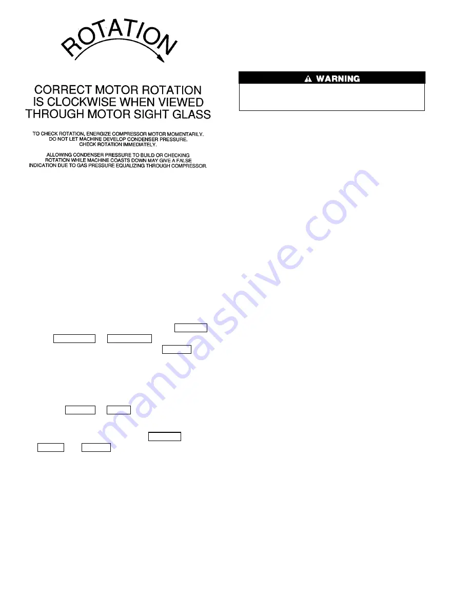
Fig. 30 — Correct Motor Rotation
60
Содержание 17
Страница 13: ...Fig 6 Open Drive 17 Series Lubrication Cycle 13 ...
Страница 15: ...Fig 7 17EX Controls and Sensor Locations 15 ...
Страница 16: ...Fig 7 17EX Controls and Sensor Locations cont 16 ...
Страница 17: ...Fig 7 17EX Controls and Sensor Locations cont 17 ...
Страница 19: ...Fig 8 19EX Controls and Sensor Locations cont 19 ...
Страница 23: ...Fig 16 17 19EX LID Menu Structure 23 ...
Страница 24: ...Fig 17 17 19EX Service Menu Structure 24 ...
Страница 50: ...Fig 28 17 19EX Leak Test Procedures 50 ...