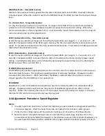
4.2 Programming Jumpers – Control Board
ARM / TACH switch (feedback mode)
Either armature or tachometer feedback is selected by the switch. The TACH position should also be
selected when the control is used as a Torque Regulator. Selection of the TACH position disconnects the
I.R. COMP pot from the circuit.
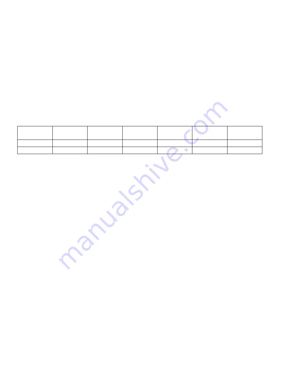
J1 (armature amps / torque range)
J1 is used to program the control according to the motor nameplate full load armature current. The
CURRENT LIMIT pots have a range up to 190% of the current level selected. Refer to the following table
to select the proper jumper location based on motor horsepower and control input voltage.
NOTE:
The 15 and 25 AMP ranges appear on the model RCP205 only.
Jumper Position
Input
Voltage
3
5
8
10
15
25
115 VAC
1/4 HP
1/2 HP
3/4 HP
1 HP
-
-
230 VAC
1/2 HP
1 HP
1 1/2 HP
2 HP
3 HP
5 HP
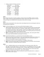
J2 (Tachometer voltage)
When operating in tachometer feedback, use J2 to select for 7 to 50 VDC/1000 RPM according to the
rating of the tachometer used.
J3 (Operating mode)
J3 selects control operation as a motor Speed Regulator or as a motor Torque Regulator. In the TORQ
position, torque is controlled by regulating armature current. For a linear motor torque with respect to
the torque reference, the voltage feedback signal should be defeated by placing the ARM/TACH switch in
the TACH position with no tachometer connected. Leaving the switch in the ARM position will cause a
non-linear torque output but will provide an upper speed limit which may be desirable in the event of
web breakage or other “runaway” conditions.
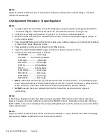
J4 (Reverse direction ACCEL/DECEL range)
The range of time set by the Reverse ACCEL and DECEL pots can be 1-5 or 4-20 seconds as determined by
the J4 jumper position.
J5 (Forward direction ACCEL/DECEL range)
The position of J5 determines the time range, 1-5 or 4-20 seconds, set by the Forward ACCEL and DECEL
pots.
4.3 Potentiometers
NOTE:
The following four potentiometers are duplicated for each direction, forward and reverse, and
each only affects operation when running in its respective direction.
Carotron RCP200 Series Page 9
Содержание RCP200 Series
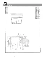
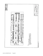
Страница 14: ...Prints 6 Carotron RCP200 Series Page 14 ...
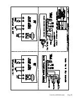
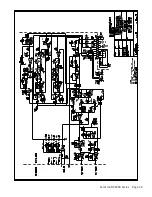
Страница 15: ...Carotron RCP200 Series Page 15 ...
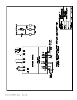
Страница 18: ...Carotron RCP200 Series Page 18 ...
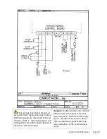
Страница 19: ...Carotron RCP200 Series Page 19 ...
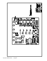
Страница 20: ...D10182 000 D10182 001 RCP200 SERIES POWER BOARD ISOLATED L1 L2 F1 F2 A1 A2 Carotron RCP200 Series Page 20 ...
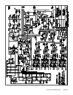
Страница 21: ...Carotron RCP200 Series Page 21 ...
Страница 22: ...Carotron RCP200 Series Page 22 ...
Страница 23: ...Carotron RCP200 Series Page 23 ...
Страница 24: ...Carotron RCP200 Series Page 24 ...
Страница 25: ...Carotron RCP200 Series Page 25 ...

