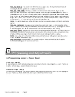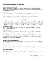
MAX (Maximum – forward & reverse)
MAX sets the maximum motor speed when the external Speed pot is set at 100%. Clockwise rotation
increases speed. When the control is used in the TORQUE mode, the MAX pot sets the maximum torque
level.
C.L. (Current limit – forward & reverse)
C.L. sets the maximum armature current level. Its range is 0 to 190% of the current level selected by
jumper J1 on the Control Board. Clockwise rotation increases the Current Limit setting. When the
control is operated as a torque regulator, the C.L. pot should be turned full clockwise since the range of
current is determined by other adjustments.
ACCEL (Acceleration time – forward & reverse)
J4 sets the reverse ACCEL pot range and J5 sets the forward ACCEL pot range to 1 - 5 seconds or 4 – 20
seconds. Clockwise rotation of the ACCEL pots increases the time to accelerate the motor linearly to full
speed. To accelerate to speeds less than full speed will take less time. To accelerate to 50% speed would
take 50% of the acceleration time.
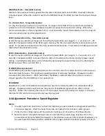
DECEL (Deceleration – forward & reverse)
J4 sets the reverse DECEL pot range and J5 sets the forward DECEL pot range to 1 – 5 seconds or 4 – 20
seconds. Clockwise rotation increases the time taken to decelerate the motor linearly to lower speed
setting. Controlled deceleration can be initiated by decreasing the speed reference or by shorting the
REF IN terminal, TB1-2, to COM, TB1-1.
IR COMP (IR compensation)
The IR COMP pot provides a signal proportional to armature current to compensate for motor losses as
the motor load increases. This improves speed regulation in armature feedback. Clockwise rotation
increases the compensation. When tachometer feedback is used and when the control is used as a
torque regulator, the IR COMP pot is not operational.
DEADBAND
Deadband is an internal feedback loop adjustment used to minimize the effect of undesirable offset
voltages. Clockwise rotation will increase the amount of deadband signal and can affect control
response. Rather than increase the amount of input signal required to produce an output, it increases
the time for the control to respond to very low input signals.
4.4 Adjustment Procedure: Speed Regulator
STEP 1:
•
Visually inspect all connections to check for tightness, proper insulation and agreement with the
connection diagram. ONLY the heatsink can be connected to the chassis or earth ground.
•
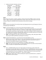
Verify the line voltage level and the positions of jumpers J1, J2 and J3 on the Power Board.
•
Note the motor nameplate full load current and select the proper range at jumper J1 on the
Control Board. Place the ARM/TACH switch in the ARM position even if tachometer feedback is to
be used. Select the desired ACCEL and DECEL time ranges with Control Board jumpers J4 and J5.
Carotron RCP200 Series Page 10
Содержание RCP200 Series
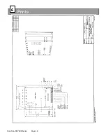
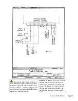
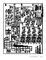
Страница 14: ...Prints 6 Carotron RCP200 Series Page 14 ...
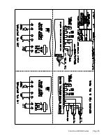
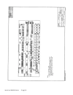
Страница 15: ...Carotron RCP200 Series Page 15 ...
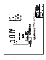
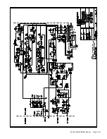
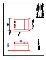
Страница 18: ...Carotron RCP200 Series Page 18 ...
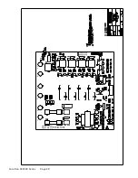
Страница 19: ...Carotron RCP200 Series Page 19 ...
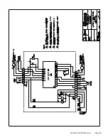
Страница 20: ...D10182 000 D10182 001 RCP200 SERIES POWER BOARD ISOLATED L1 L2 F1 F2 A1 A2 Carotron RCP200 Series Page 20 ...
Страница 21: ...Carotron RCP200 Series Page 21 ...
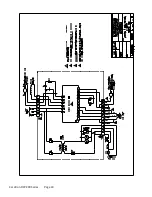
Страница 22: ...Carotron RCP200 Series Page 22 ...
Страница 23: ...Carotron RCP200 Series Page 23 ...
Страница 24: ...Carotron RCP200 Series Page 24 ...
Страница 25: ...Carotron RCP200 Series Page 25 ...

