Cargo Floor B.V.
P.O. Box 271
7740 AG COEVORDEN
The Netherlands
Phone: +31 (0)524-59 39 00 www.cargofloor.nl
Fax: +31 (0)524-59 39 99
CF500 cylinder repair regulations, Article No. 9305003
03-09-2008 / GB 9 of 26
Removing pipes
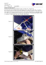
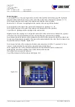
Loosen pipe P5 (see: the pipes figure below and also the assembly instructions, page H1, hydraulic
diagram and the instructions of use) on the side of the control valve (channel 4); spanners 32 + 36.
Next, loosen the pipe on the side of the common rail (rod side of the cylinder).
Remove the ¾”-20 screw-in coupling from the control valve and cap off the channel.
Loosen pipe S5 on the side of the control valve (channel A1); spanners 32 + 36.
Next, loosen the pipe on the side of the common rail (bottom side of the cylinder).
Cap off the A1 openings and the openings in the common rail.
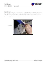
Slightly loosen the coupling screw of pipe Q5 on the side of the control valve (channel A1); spanner
32/36 (leave the nut positioned but in such a way that the pipe can turn in the coupling).
Next, loosen the nut on the side of the common rail (rod side of the cylinder) in such a way that it can
be unscrewed immediately manually). The pipe will remain attached to the valve block to ensure it can
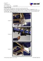
be presently used as a “handle”; figure 15.0.
Next, loosen the bolts of the common rail bottom side connection (4 x M8 x 75, spanner 13). Note:
remove 3 bolts and allow the last bolt to somewhat remain in the thread.
Now, support the valve with your hand and unscrew the last M8 bolt from the common rail.
Subsequently, loosen the coupling screw on the common rail rod side.
The control valve can now be removed.
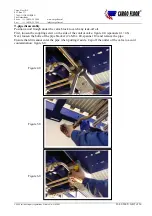
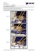
Cap off the channels of both common rails; figure 16.0
P5
Q5
S5
Figure 13.1


