Carel KEC005 Скачать руководство пользователя страница 29

15

ENG

kit OEM KEC

” +030222160 - rel. 1.0 - 03/11/2015

3.  MAINTENANCE

Maintenance carried out on the KEC at regular intervals will ensure system 
performance over time. The checks mostly involve the pumping unit, the 
distribution rack in the duct and the droplet separator, if installed, while 
the electronics do not need to be checked.
The maintenance intervals mainly depend on the quality of the 
feedwater: the higher the quantity of salts and impurities, the more 
frequently periodical checks will be required. An initial check should 
be carried out three months after starting operation, so as to ascertain 
system conditions in relation to the effective number of operating hours, 
as shown by the main air-conditioning unit controller. Based on these first 
checks, successive routine maintenance operations can be scheduled 
accordingly.

Important: before carrying out any maintenance that requires 

contact with the components in the KEC water circuit, disconnect 

power upstream using the disconnect switch installed in the main 

electrical panel.

Cabinet

• 

Replace the cartridge on the micron filter upstream of the KEC (at least 
every 3 months if using mains water).

• 

After closing the shut-off valve upstream of the KEC, check and where 
necessary clean the built-in filter on the pressure reducer. 

 - On units from 50 to 400 L/h, access the filter by unscrewing the cap 

underneath the pressure reducer, in the direction indicated by the 
arrow, shown in Fig. 3.a.

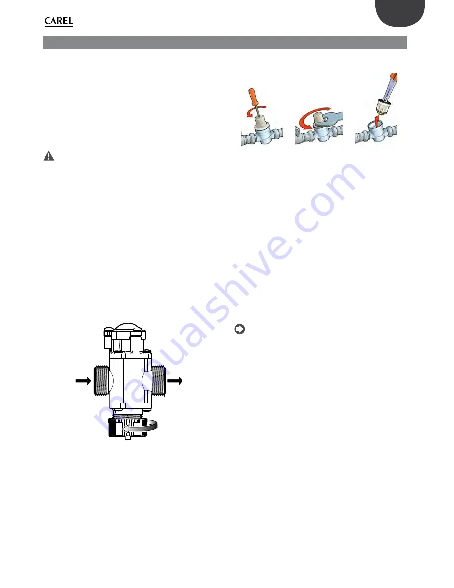
 - On units from 800 to 1000 L/h, the filter is openable from the 

pressure reducer inlet. If the filter needs cleaning, proceed as follows:

 - unscrew (counting the no. of turns) the calibration screw 

anticlockwise until releasing the spring inside (Fig. 3.b);

 - unscrew the cover (Fig. 3.c);
 - remove the cartridge using a pair of pliers (Fig. 3.d);
 - clean the filter that surrounds the cartridge;
 - reposition the cartridge, cover and calibrate the pressure reducer 

again to 3 bars.

Pressure reducer with filter on 50-400 l/h versions

INGRESSO


INLET

USCITA


OUTLET

Fig. 3.a

Pressure reducer with filter on 800-1000 l/h versions

1

2

3

Fig. 3.b 

Fig. 3.c 

Fig. 3.d 

• 

Check and if necessary clean the filter at the fill solenoid valve inlet. 
To access the filter, unscrew the plastic nut on the connector, just 
upstream of the solenoid valve.

• 

Check tightness of the tubing and water fittings in the cabinet.

• 

Make sure there are no leaks or dripping from the pump.

• 

Check operating pressure on the pressure gauges: with the pump 
running, p in ≥ 1.8 bars, p out ≤ 15 bars.

Distribution system

• 

Visually check that the nozzles atomise water when the unit is 
operating.

• 

If necessary, open the head of the nozzle by unscrewing it, and 
clean the opening using compressed air. If hard scale is present, after 
removing the O-ring, soak the nozzle head in a solution of 20% acetic 
acid in water for around 30 minutes. If necessary, replace the nozzles.

• 

Check tightness of the compression fittings, and tighten if necessary.

Droplet separator (if installed)

• 

Make sure the droplet separator is not blocked, and replace the 
modules if necessary.

Note

: The rotary vane pump does not require maintenance. If 

necessary, replace the pump when it is no longer able to deliver 

pressurised water downstream when all other conditions are equal.

Содержание KEC005

Страница 1: ...C o n t r o l S o l u t i o n s E n e r g y S a v i n g s Kit OEM KEC NO POWER SIGNAL CABLES TOGETHER READ CAREFULLY IN THE TEXT Manuale d installazione Installation manual raffreddamento evaporativo...

Страница 2: ......

Страница 3: ...arsi a contatto con l acqua o condensa d acqua CAREL Industries declina ogni responsabilit per danni conseguiti o diretti a seguito di perdite d acqua dell umidificatore Non utilizzare prodotti chimic...

Страница 4: ......

Страница 5: ...di alimento 11 2 4 Montaggio del telaio di distribuzione 11 2 5 Fissaggio della sezione elettrica 11 2 5 1 Fissaggio del controllo KEC 11 2 5 2 Fissaggio dell inverter 11 2 5 3 Fissaggio della piastra...

Страница 6: ......

Страница 7: ...che atomizza l acqua mediante ugelli 1 2 Struttura del codice della sezione idraulica K E C Prefisso famiglia Portata l h min max Tensione di alimentazione e omologazione Tipo di regolazione Elettrova...

Страница 8: ...e 10 Misuratore di portata 11 Valvola termica 12 Pompa 13 Giunto campana di fissaggio 14 Sonda temperatura 15 Sonda pressione Tab 1 c 1 5 Dimensioni peso e componenti della sezione elettrica La figure...

Страница 9: ...incauto o improprio Trasportare la sezione idraulica di KEC nel luogo di installazione prima di rimuoverla dall imballo afferrando il collo da sotto Aprire la scatola di cartone e sollevare la sezion...

Страница 10: ...cabinet per tubo Rilsan est 14 mm con attacco rapido 3 Scarico acqua vaschetta di fondo del tipo a portagomma con diametro interno 8 mm 4 Uscite acqua pressurizzata G F 5 Ingressi acqua di scarico dal...

Страница 11: ...5 40 41 104 Umidit ambiente di funzionamento rH 90 non condensante Temperatura ambiente di immagazzinamento C F 20 60 4 140 Umidit ambiente di immagazzinamento rH 90 non condensante Grado di protezion...

Страница 12: ...versioni CE codici pompa KEC DH 0 e class 2 UL per le versioni UL codici pompa KEC UH 0 classe di isolamento F o superiore fusibili di protezione secondo al primario di 4 A tipo rapido F su fase e ne...

Страница 13: ...settiera Sezione cavo mm Sezione cavo AWG Posizione foro attacco guaina Messa a terra motore PE inverter PE 2 5 14 Sinistra Alimentazione motore U inverter U 2 5 14 Sinistra V inverter V 2 5 14 Sinist...

Страница 14: ...verificare il corretto senso di rotazione del motore per garantire la produzione d acqua pressurizzata se la rotazione opposta a quella necessaria questo non avviene Attraverso il foro della campana...

Страница 15: ...caso il filtro necessitasse di pulizia le operazioni da eseguire sono svitare contando il n di giri in senso antiorario la vite di taratura fino a togliere tensione alla molla interna Fig 3 b svitare...

Страница 16: ...ter 0 4 kW 230 V per KEC005 010 020 040 1 e ECKVFD0750 Kit inverter 0 75 kW 230 V per KEC080 100 1 f KECFLOW100 Kit misuratore portata per KEC005 010 1 c 10 KECFLOW200 Kit misuratore portata per KEC02...

Страница 17: ...ndustries declines all liability for direct or indirect damage following water leaks from the humidifier Do not use corrosive chemicals solvents or aggressive detergents to clean the inside and outsid...

Страница 18: ......

Страница 19: ...characteristics 11 2 4 Assembling the distribution rack 11 2 5 Fastening the electrical system 11 2 5 1 Fastening the KEC controller 11 2 5 2 Fastening the inverter 11 2 5 3 Fastening the bottom plat...

Страница 20: ......

Страница 21: ...led which atomises the water through spray nozzles 1 2 Water circuit part number structure K E C Family prefix Flow rate l h min max Power supply and approval Type of control Rack drain solenoid valve...

Страница 22: ...re controlled valve 12 Pump 13 Fastening joint socket 14 Temperature probe 15 Pressure probe Tab 1 c 1 5 Electrical system dimensions weight and components Figures 1 d to 1 g show the overall dimensio...

Страница 23: ...sport Move the KEC water circuit to the place of installation before removing it from the packaging grasping the neck from underneath Open the cardboard box and lift the KEC water circuit holding onto...

Страница 24: ...any water hammer 2 Cabinet water drain for Rilsan tubing OD 14 mm with quick coupling 3 Bottom tank water drain ID 8 mm hose coupling 4 Pressurised water outlets G F 5 Drain water inlets from distribu...

Страница 25: ...orage temperature C F 20 to 60 4 to 140 Ambient storage humidity rH 90 non condensing Index of protection IP20 Tab 2 b 2 5 1 Fastening the KEC controller This is installed on a DIN rail and occupies 1...

Страница 26: ...s P Ns KEC DH 0 and class II UL for UL versions pumps P Ns KEC UH 0 insulation class F or higher 4 A fast blow type F protection fuses on the primary on the line and neutral F3 F4 in Figure 2 f 4 A fa...

Страница 27: ...s section AWG Position of sheath connection Motor earth PE inverter PE 2 5 14 Left Motor power supply U inverter U 2 5 14 Left V inverter V 2 5 14 Left W inverter W 2 5 14 Left Fill solenoid valve NO1...

Страница 28: ...t for the first time check correct direction of motor rotation to ensure production of pressurised water if rotation is in the opposite direction no pressurised water will be produced Check through th...

Страница 29: ...the pressure reducer inlet If the filter needs cleaning proceed as follows unscrew counting the no of turns the calibration screw anticlockwise until releasing the spring inside Fig 3 b unscrew the co...

Страница 30: ...kW 230 V inverter kit for KEC005 010 020 040 1 e ECKVFD0750 0 75 kW 230 V inverter kit for KEC080 100 1 f KECFLOW100 Flow meter kit for KEC005 010 1 c 10 KECFLOW200 Flow meter kit for KEC020 040 1 c 1...

Страница 31: ......

Страница 32: ...CAREL INDUSTRIES HQs Via dell Industria 11 35020 Brugine Padova Italy Tel 39 049 9716611 Fax 39 049 9716600 e mail carel carel com www carel com Agenzia Agency kit OEM KEC 030222160 rel 1 0 03 11 2015...

Отзывы: