Carel KEC005 Скачать руководство пользователя страница 25

11

ENG

kit OEM KEC

” +030222160 - rel. 1.0 - 03/11/2015

• 

The diameter of the feedwater inlet tubing must be greater than 
or equal to the inlet connector on the unit. The material must be 
compatible with the feedwater used (stainless steel for demineralised 
water).

• 

The water inlet lines must be flushed after installation and in any case 
before starting the unit the first time.

• 

Size the atomisation rack according to the minimum capacity of the 
pumping unit used (see Tab.1.a).

• 

Ambient operating temperature:  5...40 °C (41...104 °F)

• 

Ambient operating humidity: <90% rH non-condensing

• 

Index of protection: IP00

2.3  Feedwater characteristics

Feedwater requirements

Type/property 

Requirement

Demineralised

ü

Mains

ü


1

Softened

ü


2

Temperature °C (°F)

1 to 40 (33.8 to 104) 

4

Pressure MPa (bars)

0.3 to 0.7 (3 to 7) 

3

pH

6.5 to 8.5

Total hardness (mg/l CaCO3)

< 160

Conductivity (μS/cm) a 20°C

< 400

Tab. 2.a 

1

 The use of mains water with a total hardness and conductivity over the 

specified limits is allowed, however maintenance will need to be performed 
more frequently on the atomisation rack nozzles, heat exchanger (if present) 
and/or droplet separator (if present).

2

 To reduce aggressiveness of softened water, the minimum total hardness 

should be 20 mg/l CaCO

3

 .

3

 The range indicated in the table refers to the pump off. With the pump 

operating, pressure must not fall below 1.8 bars.

4

 A water temperature around 40°C does not improve absorption of the 

droplets in the air.

2.4  Assembling the distribution rack

See technical l0500074ML.
The drain solenoid valves on the rack

• 

should be fitted directly on the atomisation rack (P/N KEROUTV0*0, 
purchased separately) if the pumping unit P/N is KEC*****00;

• 

or are already fitted on the water circuit if the P/N is KEC*****10. In this 
case, the connection tubing between rack and drain solenoid valves 
on the pumping unit must meet the requirements for high pressure 
tubing described in paragraph 2.2.

2.5  Fastening the electrical system

The KEC controller and inverter must be installed in the air handling unit’s 
electrical panel. Table 2.b describes the limit conditions for storage and 
operation.

Specification

Value

Ambient operating  
temperature °C (°F)

5 to 40 (41 to 104)

Ambient operating  
humidity %rH

< 90 non-condensing

Ambient storage temperature °C (°F) -20 to +60 (-4 to +140)

Ambient storage humidity %rH

< 90 non-condensing

Index of protection

IP20

Tab. 2.b 

2.5.1 

Fastening the KEC controller

This is installed on a DIN rail and occupies 13 modules. Once the controller 
has been placed on the DIN rail, press it in lightly: the rear tabs will click 
into place, signifying that the controller is correctly mounted. The tabs are 
held in the locked position by return springs. To remove the controller, 
simply use a screwdriver to release and lift the tabs.
The installation position in the electrical panel must guarantee good 
physical separation between the controller and the power components 
(solenoids, contactors, actuators, inverter, ...) and the corresponding 
connection cables. The ideal situation would be to install the two circuits 
in two separate cabinets. Proximity of the two circuits may cause random 
failures that are not immediately evident. The structure of the electrical 
panel must ensure correct cooling air flow.

2.5.2 

Fastening the inverter

The inverter is secured to the EMC filter using M4 screws; the filter is in 
turn screwed onto the electrical panel using M5 screws. Leave clearance 
of at least 30 mm on the right and left, and at least 100 mm at the top and 
bottom, so as to guarantee sufficient ventilation. The installation position 
in the electrical panel must guarantee good physical separation between 
the power cable and the serial cable running between the inverter and 
KEC controller. Admissible pollution degree is ≤ 2 in accordance with UL 
and EN 61439-1.

2.5.3 

Fastening the bottom plate (if featured)

If the KEC controller and inverter are supplied already assembled on 
the bottom plate, the complete plate then installed inside the electrical 
panel. 

2.6  Electrical connections

The electrical connections are the responsibility of the OEM, except for 
the wiring from the terminal block to the electromechanical components 
in the water circuit. The maximum length of the electrical connections 
between the electrical components and the water circuit is 15 m.
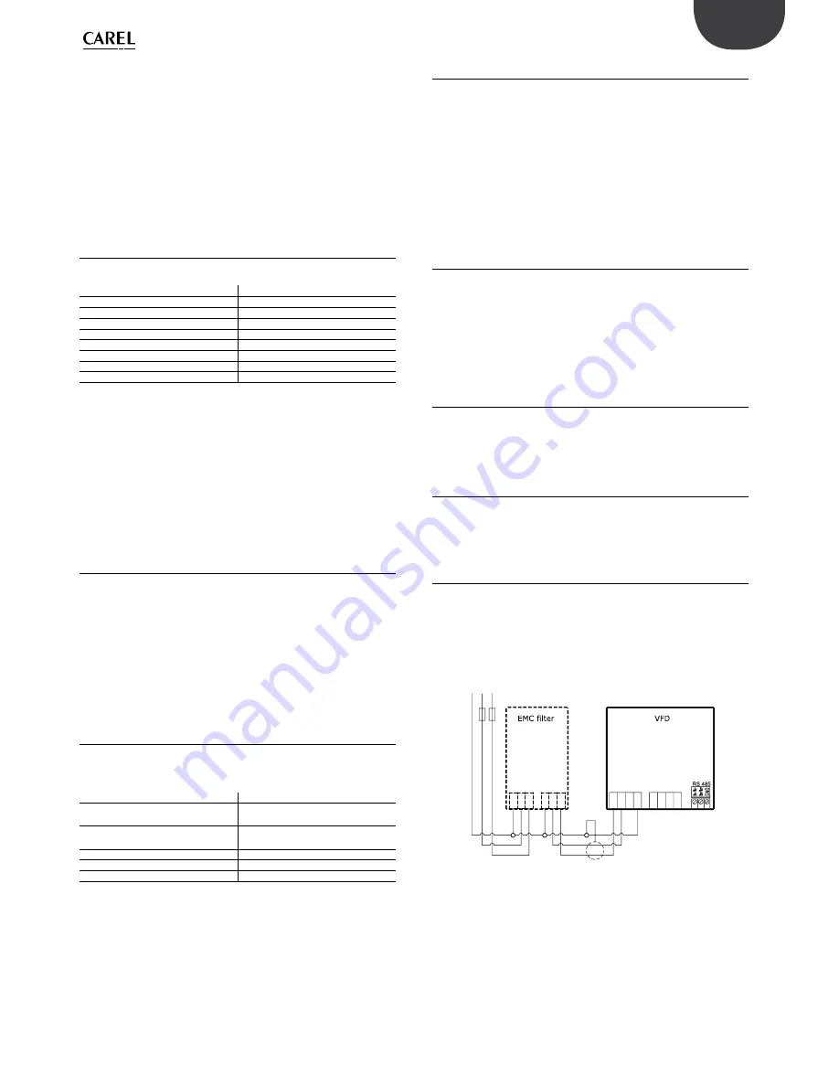
2.6.1 

Inverter power supply

The power supply, to be provided by the user, is:

• 

230 Vac single-phase 50/60 Hz + earth for pumps P/Ns KEC***D***;

• 

230 Vac single-phase 50/60 Hz + earth for pumps P/Ns KEC***U***.

This is connected to the inverter filter (L, N, PE) and then from there to the 
inverter (L1, L2, PE), as shown in Fig. 2.e.

Inverter 230 Vac wiring

L3

L

N

PE

L

N

PE

F1

PE

PE

W

V

U

L2

L1

F2

PE N L

Fig. 2.e

Содержание KEC005

Страница 1: ...C o n t r o l S o l u t i o n s E n e r g y S a v i n g s Kit OEM KEC NO POWER SIGNAL CABLES TOGETHER READ CAREFULLY IN THE TEXT Manuale d installazione Installation manual raffreddamento evaporativo...

Страница 2: ......

Страница 3: ...arsi a contatto con l acqua o condensa d acqua CAREL Industries declina ogni responsabilit per danni conseguiti o diretti a seguito di perdite d acqua dell umidificatore Non utilizzare prodotti chimic...

Страница 4: ......

Страница 5: ...di alimento 11 2 4 Montaggio del telaio di distribuzione 11 2 5 Fissaggio della sezione elettrica 11 2 5 1 Fissaggio del controllo KEC 11 2 5 2 Fissaggio dell inverter 11 2 5 3 Fissaggio della piastra...

Страница 6: ......

Страница 7: ...che atomizza l acqua mediante ugelli 1 2 Struttura del codice della sezione idraulica K E C Prefisso famiglia Portata l h min max Tensione di alimentazione e omologazione Tipo di regolazione Elettrova...

Страница 8: ...e 10 Misuratore di portata 11 Valvola termica 12 Pompa 13 Giunto campana di fissaggio 14 Sonda temperatura 15 Sonda pressione Tab 1 c 1 5 Dimensioni peso e componenti della sezione elettrica La figure...

Страница 9: ...incauto o improprio Trasportare la sezione idraulica di KEC nel luogo di installazione prima di rimuoverla dall imballo afferrando il collo da sotto Aprire la scatola di cartone e sollevare la sezion...

Страница 10: ...cabinet per tubo Rilsan est 14 mm con attacco rapido 3 Scarico acqua vaschetta di fondo del tipo a portagomma con diametro interno 8 mm 4 Uscite acqua pressurizzata G F 5 Ingressi acqua di scarico dal...

Страница 11: ...5 40 41 104 Umidit ambiente di funzionamento rH 90 non condensante Temperatura ambiente di immagazzinamento C F 20 60 4 140 Umidit ambiente di immagazzinamento rH 90 non condensante Grado di protezion...

Страница 12: ...versioni CE codici pompa KEC DH 0 e class 2 UL per le versioni UL codici pompa KEC UH 0 classe di isolamento F o superiore fusibili di protezione secondo al primario di 4 A tipo rapido F su fase e ne...

Страница 13: ...settiera Sezione cavo mm Sezione cavo AWG Posizione foro attacco guaina Messa a terra motore PE inverter PE 2 5 14 Sinistra Alimentazione motore U inverter U 2 5 14 Sinistra V inverter V 2 5 14 Sinist...

Страница 14: ...verificare il corretto senso di rotazione del motore per garantire la produzione d acqua pressurizzata se la rotazione opposta a quella necessaria questo non avviene Attraverso il foro della campana...

Страница 15: ...caso il filtro necessitasse di pulizia le operazioni da eseguire sono svitare contando il n di giri in senso antiorario la vite di taratura fino a togliere tensione alla molla interna Fig 3 b svitare...

Страница 16: ...ter 0 4 kW 230 V per KEC005 010 020 040 1 e ECKVFD0750 Kit inverter 0 75 kW 230 V per KEC080 100 1 f KECFLOW100 Kit misuratore portata per KEC005 010 1 c 10 KECFLOW200 Kit misuratore portata per KEC02...

Страница 17: ...ndustries declines all liability for direct or indirect damage following water leaks from the humidifier Do not use corrosive chemicals solvents or aggressive detergents to clean the inside and outsid...

Страница 18: ......

Страница 19: ...characteristics 11 2 4 Assembling the distribution rack 11 2 5 Fastening the electrical system 11 2 5 1 Fastening the KEC controller 11 2 5 2 Fastening the inverter 11 2 5 3 Fastening the bottom plat...

Страница 20: ......

Страница 21: ...led which atomises the water through spray nozzles 1 2 Water circuit part number structure K E C Family prefix Flow rate l h min max Power supply and approval Type of control Rack drain solenoid valve...

Страница 22: ...re controlled valve 12 Pump 13 Fastening joint socket 14 Temperature probe 15 Pressure probe Tab 1 c 1 5 Electrical system dimensions weight and components Figures 1 d to 1 g show the overall dimensio...

Страница 23: ...sport Move the KEC water circuit to the place of installation before removing it from the packaging grasping the neck from underneath Open the cardboard box and lift the KEC water circuit holding onto...

Страница 24: ...any water hammer 2 Cabinet water drain for Rilsan tubing OD 14 mm with quick coupling 3 Bottom tank water drain ID 8 mm hose coupling 4 Pressurised water outlets G F 5 Drain water inlets from distribu...

Страница 25: ...orage temperature C F 20 to 60 4 to 140 Ambient storage humidity rH 90 non condensing Index of protection IP20 Tab 2 b 2 5 1 Fastening the KEC controller This is installed on a DIN rail and occupies 1...

Страница 26: ...s P Ns KEC DH 0 and class II UL for UL versions pumps P Ns KEC UH 0 insulation class F or higher 4 A fast blow type F protection fuses on the primary on the line and neutral F3 F4 in Figure 2 f 4 A fa...

Страница 27: ...s section AWG Position of sheath connection Motor earth PE inverter PE 2 5 14 Left Motor power supply U inverter U 2 5 14 Left V inverter V 2 5 14 Left W inverter W 2 5 14 Left Fill solenoid valve NO1...

Страница 28: ...t for the first time check correct direction of motor rotation to ensure production of pressurised water if rotation is in the opposite direction no pressurised water will be produced Check through th...

Страница 29: ...the pressure reducer inlet If the filter needs cleaning proceed as follows unscrew counting the no of turns the calibration screw anticlockwise until releasing the spring inside Fig 3 b unscrew the co...

Страница 30: ...kW 230 V inverter kit for KEC005 010 020 040 1 e ECKVFD0750 0 75 kW 230 V inverter kit for KEC080 100 1 f KECFLOW100 Flow meter kit for KEC005 010 1 c 10 KECFLOW200 Flow meter kit for KEC020 040 1 c 1...

Страница 31: ......

Страница 32: ...CAREL INDUSTRIES HQs Via dell Industria 11 35020 Brugine Padova Italy Tel 39 049 9716611 Fax 39 049 9716600 e mail carel carel com www carel com Agenzia Agency kit OEM KEC 030222160 rel 1 0 03 11 2015...

Отзывы: