


docs.carbide3d.com
8/26/2020
Version 1.0
28
Connect the Wiring
Connect the Motors
1.
Connect the X- and Z-motor lead cables to their labeled extension cables at the rear of the Z-Plus.
a.
Both the X- and Z-motor extensions exit the head of the X-Axis drag chain behind the Z-Plus.
b.
Connectors are polarized. Be sure to align them properly.
2.
Connect the Y1- and Y2- motor lead cables to their extension cables.
a.
Both the Y1- and Y2-motor extensions exit the head of the Y-Axis drag chain at the Y1-carriage.
b.
The Y2-motor lead cable stretches across the machine, behind the X-rail.
c.
Connectors are polarized. Be sure to align them properly.
Connect Cables to the Carbide Motion Board
Z-Plus Upgrade Kit:
Item
Description
Qty
I
Riser Board
1
Shapeoko XXL and XL Instructions
1.
Plug the PCB riser board into the Carbide Motion
board. See
Fig. 31
.
a.
Plug the PCB riser board into the 2
×
8 open
bank of pins in the top-right of the Carbide
Motion board.
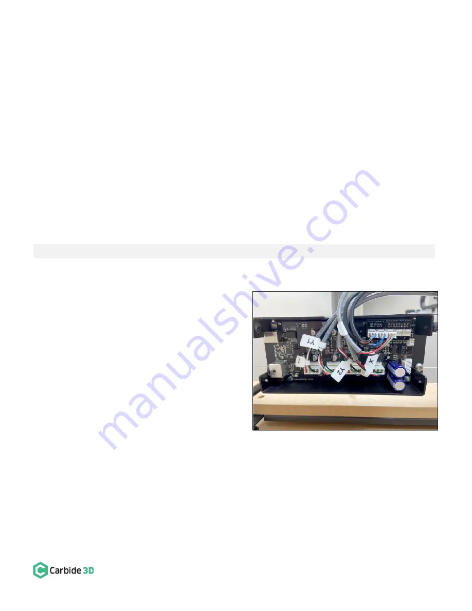
2.
Plug the proximity switch cables and stepper
motor extension cables into the Carbide Motion
board. See
Fig. 31
.
a.
Plug each of the 3-pin proximity switch
cables, X, Y, and Z, into the PCB riser
board, as labeled.
b.
Plug each of the 4-pin motor extension
cables Z, Y1, Y2, X, into the connectors
across the bottom of the Carbide Motion board, as labeled.
c.
Connectors are polarized. Be sure to align them properly.
Figure 31


