background image


19/33 


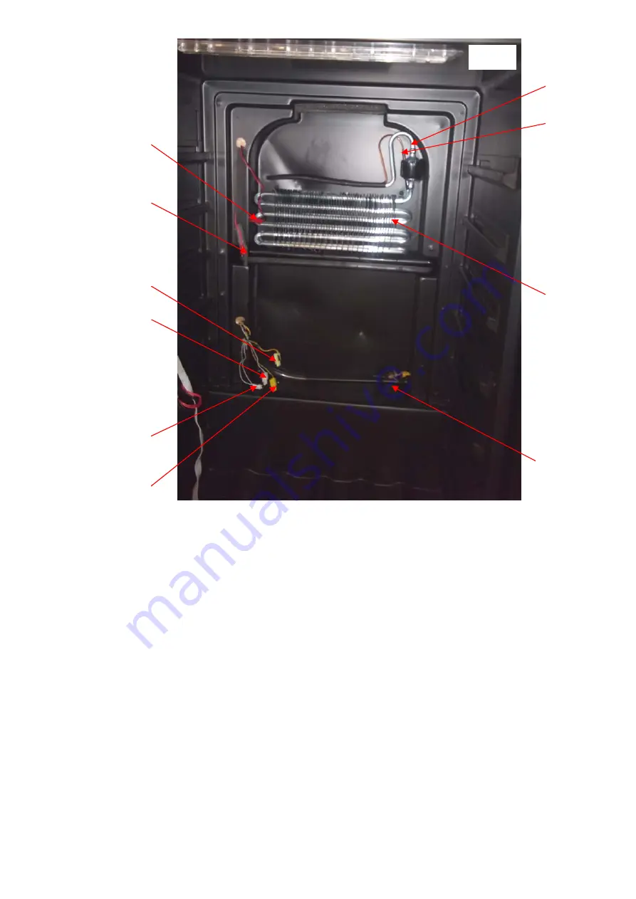
6.1.3.How to remove the evaporator 

The process: Remove the shelves→Remove the control panel film→Remove the screws→

Remove the display supporter  →Remove the middle electrical box→  Remove the screws

→Remove the upper and lower air-duct board.→  Remove the inner air-duct board 

→  separate the evaporator from the compressor and dry filter on the joints. 


You can see the evaporator is joint to suction pipe and capillary.


(Fig.7  )

Heat  the  joint  E,G


(Fig.17  ) 

in the compressor room, and disconnect the pipe from compressor by using the 

plier. Then remove the evaporator and capillary and suction pipe upward.


Fig.7


Содержание WC6216

Страница 1: ...WC6216 Caple 60cm in column wine cabinet Technical information ...

Страница 2: ......

Страница 3: ...DG13 7 Shelf support 1 DG20 1 Wire clamp 1 DG8 8 senser 1 17 DG7 3 1 BH Evaporator fan 1 18 DG22 498 Air duct board 1 19 DG22 499 Upper panel for air leaded board 1 20 DG22 3000 middle airway board 1 21 DG18 98 Foam 1 22 DG13 469 Display support 1 23 DG20 261 Display panel 1 DG15 205 1 Wooden shelves 1 DG15 205 Wooden shelves 4 25 DG13 1 2 Humid box 1 26 DG23 210 door 1 27 M147 005 gasket 1 28 DG2...

Страница 4: ... hinge module 1 38 DG13 475 Reed switch 1 39 DG22 3014 Lid of reed switch 1 40 DG13 474 support bar 2 41 DG22 3005 Electrical box cove 1 42 DG22 473 strengthening board 1 43 DG3 13 W LED light 1 44 DG13 129 LED light cover 1 45 DG11 18 PTC heater 1 46 DG3 18 W LED Light 1 47 DG11 4 Drier 1 DG13 3031 Hinge pin clip cover DG22 475 Hinge pin ...

Страница 5: ......

Страница 6: ...ning or maintenance this unit MUST be disconnected from the electrical supply to prevent electrical shock Preparation before maintenance Tools 1 Pliers 2 Phillips head screwdrivers 3 Process pipe 4 Electrical Multi meter 5 Amp meter 5A caliper cable type 6 Electrical soldering iron 7 Wire strippers 8 Seal pliers Equipment 1 Vacuum pump 2 Soldering iron for copper pipes 3 Refrigerant meter 1 Safety...

Страница 7: ...ow we list the symbols and explain the danger if ignore it Danger This symbol means that the instance may have the chance to suffer death or a serious wound Warning This symbol means that the instance may have the chance to suffer death or a serious wound Notice This symbol means that the instance may have the chance to suffer a wound Below symbols distinguish and rules should be obeyed This symbo...

Страница 8: ...n the systems and cause blast Exhaust the rest refrigerant in the systems before welding After filling the refrigerant the sealing should be done by using smithing welding nozzle Using the welding machine will fire the refrigerant and blast Since the R600a is heavier than the air please let the R600a on the ground go especially for the hypogeum The operation on the servicing refrigerant bottle sho...

Страница 9: ...c shock When checking current voltage or charging never touch the connectors When changing the parts don t touch the charged parts within three minutes after disconnect the plug The capacitor will discharge for some time Don t damage the cooling pipe sine the refrigerant is flammable the damage will cause the fire or blast Don t smoking in the service car ...

Страница 10: ...t the maximum leaning angle is 40 Do use the appointed part otherwise it have chance to smoke fire or default Please put the default compressor into plastic bag and seal the peristome then pack it with strip as the rest compressor oil may leak in the vehicle and cause fire or blast Check if all the snails parts wiring are install in it s place if the area around the service part worsen When measur...

Страница 11: ...the welding Attention the refrigerant during charge and discharge it as it will frostbite the skin when touch it Attention the burr The burr on the metal or plastic part may hurt the hand Attention the fins of the evaporator The fins of the evaporator may hurt the hand Drive up the wine cooler when moving it Pushing it may damage the floor Cover a protector board on the easy damage floor 2 Electri...

Страница 12: ...7 33 3 Cooling system diagram ...

Страница 13: ...it is not effect by the door switch Press it and hold on for three seconds will enter the time adjustment Press adjust the hour press adjust the minute Press it one time the power on press it and hold on for three seconds the power off z The default setting temp of this wine cooler are upper compartment6 lower compartment 12 but when restart the wine cooler after power off it will back to the form...

Страница 14: ...ng by the self check mode The wine cooler is controlled by computer in order to maintain the wine cooler easily there is a self check function in the control PCB If you suspect that the control system fault you can star the self check mode by following below 1 Power on the wine cooler it will beep one sound the wine cooler star within 10 seconds after it star press the and at the same time and hol...

Страница 15: ...ircuit Check the wiring and connection between PCB and sensor if it short circuit If the connection and wiring is normal replace the sensor please E7 Lower compartment sensor open circuit Check the wiring and connection between PCB and sensor if it open circuit If the connection and wiring is normal replace the sensor please E8 Lower compartment sensor short circuit Check the wiring and connection...

Страница 16: ...5 minutes the readout show LO the buzzer alarm and the compressor stop at the same time when the inner temperature is over 2ºC the LO warning stop Remark some models without the HI and LO warning function 5 3 Diagnose the defaults There isn t any display on the display PCB Not cooling the compressor stop Yes Yes If the inner light can be turn on Check the power source power cord plug socket Check ...

Страница 17: ...Yes Yes No If the inner light can be turn on Check the power source power cord plug socket Display error code Refer to 5 2 The starter have power input The protector have power input Check the compressor The starter failed The protector failed Compressor fault ...

Страница 18: ...on the out of the guiding rail then pull the shelf out Fig 1 6 1 2 How to remove the air duct board No Yes No Yes No No Yes The compressor run for more than 30 minutes If the door opened frequently Don t open the door frequently If the hot goods was put into the cabinet If the door gasket airproof Cooling system default Check if any gas leakage or block It can be loaded with normal temperature win...

Страница 19: ...Remove control panel film Remove all shelves then peel off the control panel film Be careful don t damage the control panel file as it have to be fixing again Fig 2 2 Remove the display supporter The process Remove the shelves Remove the control panel film Remove the screws Remove the display supporter Remove the shelves after removing the control panel film Fig 2 remove the screws A and B disconn...

Страница 20: ...e screws Remove the display supporter Remove the middle electrical box Remove the shelves remove the control panel and display supporter Fig 2 Fig 3 Remove the four middle electrical box fixing screws disconnect the light connecter remove the middle electrical box Fig 4 Screws B Screws A Display connector Fig 3 ...

Страница 21: ...emove the screws Remove the upper and lower air duct board Remove the shelves remove the control panel and display supporter Fig 2 Remove the four middle electrical box fixing screws disconnect the light connecter remove the middle electrical box Fig 4 remove the middle air duct board fixing screws remove the middle air duct board Fig 5 Middle electrical box LED light connector Screws Fig 4 ...

Страница 22: ...ay supporter Remove the middle electrical box Remove the screws Remove the upper and lower air duct board Remove the inner air duct board 1 After remove the upper and lower air duct board remove the inner air duct board fixing screws and then remove the inner air duct board Upper air duct board Lower air duct board Screws Screws Fig 5 ...

Страница 23: ...ig 7 A Capillary solder joint B Suction pipe solder joint C Upper compartment fan connector D Upper compartment sensor connector E Heater fan connector F Heater connector G Defrost sensor connector H Air cycling fan connector I Lower compartment sensor J evaporator Screws Inner air duct board Fig 6 ...

Страница 24: ...he upper and lower air duct board Remove the inner air duct board separate the evaporator from the compressor and dry filter on the joints You can see the evaporator is joint to suction pipe and capillary Fig 7 Heat the joint E G Fig 17 in the compressor room and disconnect the pipe from compressor by using the plier Then remove the evaporator and capillary and suction pipe upward Fig 7 C D E F G ...

Страница 25: ...emove the inner fan The process Remove the shelves Remove the control panel film Remove the screws Remove the display supporter Remove the middle electrical box Remove the screws Remove the upper and lower air duct board Remove the inner air duct board Remove the fan fixing screws Remove the fan After remove the inner air duct board remove the fans fixing screws and we can remove the fan Fig 9 Dis...

Страница 26: ... duct board Remove the inner air duct board Remove the heater fixing screws Remove the heater After removing the air duct board the heater is on the back of it remove the fixing screws and we can remove the heater Fig 10 6 1 7 How to remove the defrost sensor and upper compartment sensor Front of the inner air duct board front Fan 1 Fan 2 Fan 3 Screws Screws Screws Fig 9 Screws Heater Back of the ...

Страница 27: ...ove the sensor Remove the shelves remove the lower air duct board we can see the lower compartment sensor remove the sensor fixing screw and remove the sensor Fig 7 6 1 8 How to remove the LED light 1 How to remove the lower compartment LED light The process Remove the shelves Remove the control panel film Remove the screws Remove the display supporter Remove the PCB Remove the shelves peel off th...

Страница 28: ...ws Remove the LED light Remove the shelves Fig 1 Remove two light cove fixing screws remove the light cover Fig 13 Remove the LED light fixing screw in the middle of it remove the LED light Fig 13 1 6 2 Gist on disassembly outside the cabinet Fig 13 1 Middle electrical box Foam in the middle electrical box LED light connector LED light Fig 12 Screws Screw Fig 13 Fig 12 1 Nails ...

Страница 29: ...r box Fig 14 1 Remove the two transformer fixing screws Fig 14 1 6 2 2 How to remove the main PCB The process of removing power box Remove the power box Disconnect the connectors on the main PCB Remove the main PCB After disconnect the connectors press the head of the PCB supporting nails one by one and remove the main PCB at the same time Fig 15 Screws Transformer Screw Barbs Main PCB Fig 14 Fig ...

Страница 30: ...25 33 Diagram of main PCB connection Fig 16 Fig 15 Main PCB Four barbs fixing PCB ...

Страница 31: ...s of removing the compressor Remove the electrical cover of compressor disconnect the connectors separate the pipe connect to the compressor remove the compressor Heat E F with soldering iron and disconnect the pipes by using the plier Remove the electrical cover of the compressor and then remove four compressor fixing screws remove the compressor Fig 17 Diagram of rear soldering joints Fig 17 A J...

Страница 32: ... the outer condenser Remove four fixing screws Remove the outer condenser Separate on A H by Soldering iron for copper pipes separate the pipe using the plier remove four screws J remove the condenser K Fig 17 7 How to overhaul the faults It should take approximate 3 hours to reach the lowest setting temperature of about 5 or 4 for an A B C E F G H J K Fig 17 I D ...

Страница 33: ... and the cooling system s fault is concentrating on the cooling system pipe Check following below 1 Cut off process pipe and check the refrigerant If there is not enough refrigerant the default of the refrigerant system should be caused by the leaking If the refrigerant is sufficient it is probably block in the capillary 2 If the default is concentrated on the cooling system the checking procedure...

Страница 34: ... approximately 20 minutes Until the vacuum is lower than 100Pa Then solder the process pipe of the filter Keep the vacuum running while soldering this joint 2 Fill Cooling system with refrigerant via the process pipe of the compressor Fig 17 showing B Regarding refrigerant quantity Please refer to the instruction at back label of wine cellar Then solder the compressor process pipe after the system...

Страница 35: ...illary Reason The end of the capillary is in the wrong position or there are rough edges on the end of the capillary Solution 1 Remove the evaporator 6 1 3 heat the soldered joint of the capillary Fig 7 then remove the capillary from the evaporator and smooth the end with an eraser Caution do not allow any particles into capillary unit 2 Replace the capillary into the evaporator then solder it bac...

Страница 36: ...7 9 Evaporator freezing Because the door seal is not air proof or the door is not closed well cause much water fill in the cabinet and the water got frozen when it encounter the cold air sometimes the ice is too thick and it will block the fan or broken the fan The solution 1 Replace the door seal or close the door well If the door seal is slightly not air proof it can be repaired by the heat drye...

Страница 37: ...an of the same model 6 1 4 7 11 The digital display s fault This malfunction is caused by the display panel s default replace with the same model s display panel 6 2 1 7 12 Door switch fault 1 Check if the X1 well connected Fig 16 if it ok replace the switch please 2 Remove the switch box fixing screws and cut the switch Fig 19 Fig 19 1 3 Peel off the scarfskin on the end about 12mm cut the spare ...

Страница 38: ...If above process finis it still fault that means the wiring damaged in the foam you have to have another wiring along the bottom and back of the cabinet to connect the switch Rev A 12mm strip 4 Insulating tape ...

Отзывы: