CHAPTER 3 EXPOSURE SYSTEM
COPYRIGHT © 1999 CANON INC. CANON NP6317 REV.0 APR. 1999 PRINTED IN JAPAN (IMPRIME AU JAPON)
3-19
D.
Blank Assembly
1.
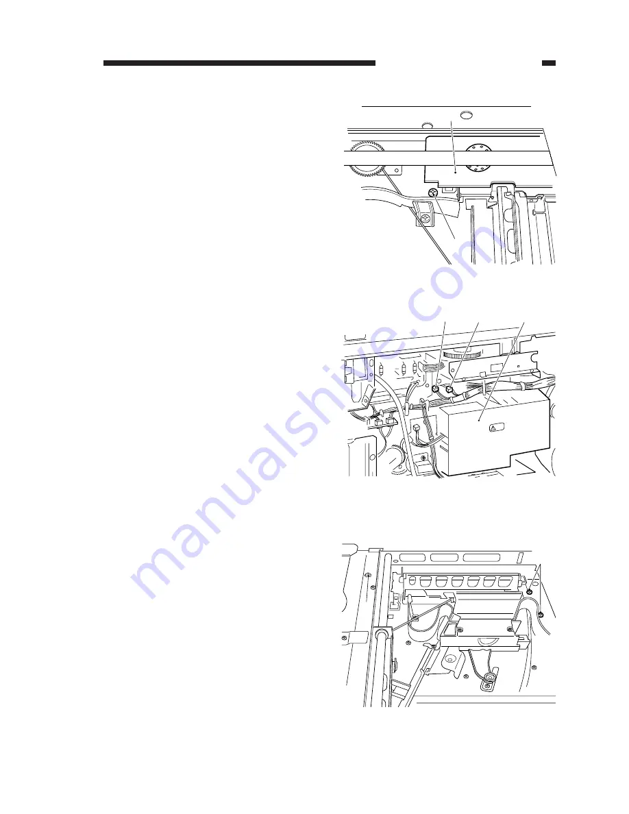
Detaching the Pre-Exposure PCB
1) Detach the rear cover.
2) Disconnect the connector (J731) from the
pre-exposure PCB.
3) Hold the pre-exposure PCB using pliers,
and pull it straight out taking care not to
damage the PCB.
2.
Detaching the Blank Assembly
1) Detach the copyboard glass, lens cover,
lens motor cover, rear cover, and drum
unit; then, detach the developing assem-
bly.
2) Disconnect the connector (J731) from the
pre-exposure PCB and the connector
(J30) from the blank solenoid.
3) Holding the blank assembly on its bottom,
and remove the four screws; then, pull out
the pre-exposure lamp to the front.
[2]
[1]
[1]
[3]
[2]
[1]
[1]
[1] Lens motor cover [2] Screw
Figure 3-513
[1] Connector (J731) [2] HVT
[3] Connector (J30)
Figure 3-514
[1] Screws
Figure 3-515
Содержание NP6317
Страница 4: ......
Страница 10: ......
Страница 22: ......
Страница 24: ......
Страница 36: ......
Страница 58: ......
Страница 90: ......
Страница 112: ......
Страница 128: ......
Страница 130: ......
Страница 142: ......
Страница 144: ......
Страница 158: ......
Страница 187: ......
Страница 236: ......
Страница 238: ......
Страница 242: ......
Страница 244: ......
Страница 246: ......
Страница 248: ...0499AB0 91 1 PRINTED IN JAPAN IMPRIME AU JAPON This pubication is printed on 70 reprocessed paper ...


