CHAPTER 2 BASIC OPERATION
COPYRIGHT © 1999 CANON INC. CANON NP6317 REV.0 APR. 1999 PRINTED IN JAPAN (IMPRIME AU JAPON)
2-6
D.
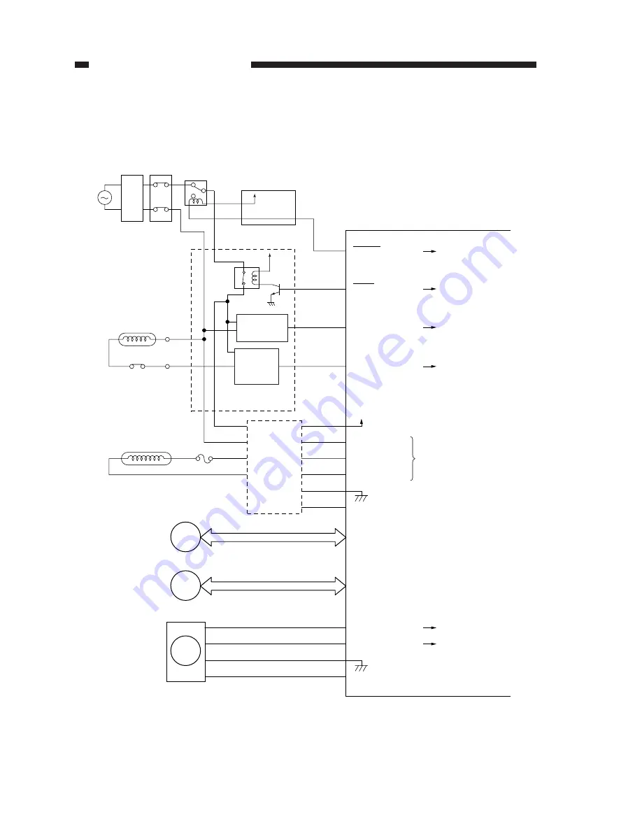
DC Controller Outputs
1.
DC Controller Out Puts (1/3)
Figure 2-105
DC controller PCB
J301-1
-2
MMD
MMLOCK
-4
-3
J351-1
-2
-4
-3
+24V
Mirror motor
Main motor
M3
M1
J318-3
J316-11
J503-1
J509-2
J509-1
HTPT
when "0"
AC power OFF (power
supply unit).
PWOFF
when "0"
AC power OFF (main
switch).
when "0"
main motor is moving.
when "1"
See p. 3-9.
main motor ON.
24V
J305
-6
-3
LAMP-CHECK
-4
-2
ZERO-CROSS
-5
LIGHT
LAMP-SHIFT
J201-1
-2
-1
J202-3
-1
J203
-1
-4
-3
-5
-2
-6
Lamp driver unit
Scanning lamp
F2
LA2
Scanner motor
M2
See p. 3-9.
See p. 3-20.
-1
J4-1
HTRD
when "1"
fixing roller heater ON.
Fixing roller heater
Thermoswitch 1
Thermoswitch 2
LA1
F1
-2
DS1
SW1
Noise
filter
24V
K100
24V
-2
HTCK
when "0"
fixing roller heater ON.
Fixing heater
ON detection
circuit
Fixing
heater drive
circuit
Power supply
assembly
Control panel PCB
Содержание NP6317
Страница 4: ......
Страница 10: ......
Страница 22: ......
Страница 24: ......
Страница 36: ......
Страница 58: ......
Страница 90: ......
Страница 112: ......
Страница 128: ......
Страница 130: ......
Страница 142: ......
Страница 144: ......
Страница 158: ......
Страница 187: ......
Страница 236: ......
Страница 238: ......
Страница 242: ......
Страница 244: ......
Страница 246: ......
Страница 248: ...0499AB0 91 1 PRINTED IN JAPAN IMPRIME AU JAPON This pubication is printed on 70 reprocessed paper ...