


2
2
2-12
2-12
Technical Overview > Laser Exposure System > Controlling the Laser Activation Timing > Horizontal Sync Control
Technical Overview > Laser Exposure System > Controlling the Laser Activation Timing > Horizontal Sync Control
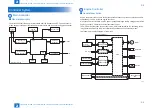
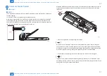
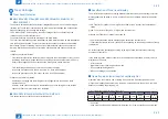
Controlling the Laser Activation Timing
■
Laser ON/OFF Control
In this control, the laser driver turns on/off the 2 laser diodes (LD1, LD2) according to the
laser control signal sent from the engine controller.
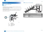
The following is the circuit diagram of the laser control.
Logic circuit
PD
LD1
Engine
controller PCB
Laser driver PCB
Laser driver IC
IC102
ASIC
GND
VCC
BD PCB
/BDI
J116-2
J31-2
LD2
LD1
switching
circuit
VDO1
/VDO1
VDO2
/VDO2
CNT0
CNT1
CNT2
Standard voltage
Comparator
Sample
hold circuit
C18
C16
PDOUT
J11
-1
J102
-13
-2
-4
-8
-10
-12
-10
-6
-4
-11
-3
-5
-6
-7
-9
-8
-7
-3/9/12
-2/5/11
IC101
CPU
Comparator
Sample
hold circuit
+5V
LD2
switching
circuit
F-2-15
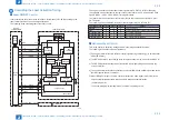
The engine controller sends the laser control signals (CNT0, CNT1, CNT2) for changing
the operation mode of the laser to the logic circuit in the laser driver IC, as well as the video
signals (VDO1, /VDO1, VDO2, /VDO2) for image formation.
The laser driver IC executes laser control according to the combination of the CNT0, CNT1,
CNT2 signals.
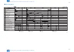
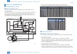
The following is the combination of the laser control signal (CNT0, CNT1, CNT2).
Operation mode CNT0
CNT1
CNT2
Details
Standby
L
L
L
Laser control OFF
H
H
H
Can emit the laser according to the video signal
LD1 forced ON
L
H
L
LD1 forcibly turned ON
LD2 forced ON
H
L
L
LD2 forcibly turned ON
LD forced OFF
H
H
L
LD1, LD2 forcibly turned OFF
■
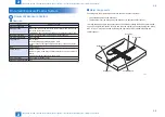
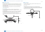
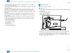
Horizontal Sync Control
This is the control to adjust the writing position in the image horizontal direction.
The following is the details of control procedure.
1) The engine controller controls the laser control signal during unblanking (*) to emit the laser
diode (LD) forcibly.
2) The BD PCB exists on the scanning route of the laser beam, which is sent to the BD PCB.
3) The BD PCB detects this laser beam, creates BD input signal (/BDI) and sends it to the
engine controller.
4) The engine controller creates horizontal sync signals (/BD) based on /BDI signal and sends
the /BD signal to the main controller.
5) When /BD signal is input, the main controller outputs the video signal (VD0, /VD0) to the
engine controller to adjust the writing position in image horizontal direction.
*: Unblanking period
The period during which the laser diode is emitted in non-image area.
T-2-3
Содержание MF4500 Series
Страница 15: ...1 1 Product Overview Product Overview Product Lineups Features Product Specifications Name of Parts ...
Страница 222: ...5 5 Adjustment Adjustment Mechanical Adjustment ...
Страница 224: ...6 6 Trouble Shooting Trouble Shooting Test Print Trouble Shooting Items Version Upgrade ...
Страница 230: ...7 7 Error Codes Error Codes Overview Error Codes ...
Страница 234: ...8 8 Service Mode Service Mode Overview COPIER FEEDER FAX TESTMODE ...
Страница 251: ... Service Tools Solvent Oil List General Circuit Diagram General Timing Chart Appendix ...


