


4
4
4-85
4-85
Disassembly/Assembly > Controller System > Removing the Main Motor Single-sided models (MF4450/MF4452/MF4453/MF4430/MF4420n/MF4410/MF4412)
Disassembly/Assembly > Controller System > Removing the Main Motor Single-sided models (MF4450/MF4452/MF4453/MF4430/MF4420n/MF4410/MF4412)
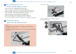
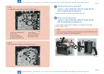
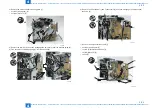
Caution:
Align the drive cover [2] with the 14 shaft holes [1] to mount it.
[1]
[1]
[1]
[2]
F-4-195
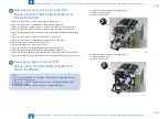
Before Removing the Main Motor
Single-sided models (MF4450/MF4452/MF4453/
MF4430/MF4420n/MF4410/MF4412)
1) Remove the left cover. (Single-sided models) (Refer to page 4-32)
2-1) Remove the SADF unit and reader unit. (models with SADF) (Refer to page 4-53)
2-2) Remove the copyboard cover and reader unit. (models with copyboard)(Refer to page
3) Remove the right cover. (Single-sided models) (Refer to page 4-34)
4) Remove the front cover unit. (Refer to page 4-35)
5) Remove the upper cover. (Refer to page 4-35)
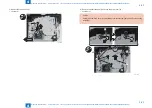
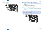
Removing the Main Motor
Single-sided models (MF4450/MF4452/MF4453/
MF4430/MF4420n/MF4410/MF4412)
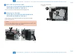
1) Remove the scanner cover [1].
• 2 screws (black TP) [2]
[1]
[2]
x2
F-4-196
Содержание MF4500 Series
Страница 15: ...1 1 Product Overview Product Overview Product Lineups Features Product Specifications Name of Parts ...
Страница 222: ...5 5 Adjustment Adjustment Mechanical Adjustment ...
Страница 224: ...6 6 Trouble Shooting Trouble Shooting Test Print Trouble Shooting Items Version Upgrade ...
Страница 230: ...7 7 Error Codes Error Codes Overview Error Codes ...
Страница 234: ...8 8 Service Mode Service Mode Overview COPIER FEEDER FAX TESTMODE ...
Страница 251: ... Service Tools Solvent Oil List General Circuit Diagram General Timing Chart Appendix ...


