2
2
2-11
2-11
Technical Overview > Laser Exposure System > Overview > Overview
Technical Overview > Laser Exposure System > Overview > Overview
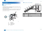
Laser Exposure System
Overview
■
Overview
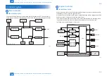
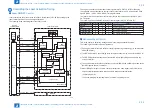
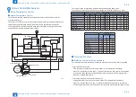
The laser exposure system forms static latent images on the photosensitive drum according
to the VIDEO signals sent from the main controller, and is comprised of the laser driver and
scanner motor, etc. These are controlled by the engine controller. The following is the outline.
Laser unit
Scanner motor unit
Four-faced mirror
Cylindrical lens
Photosensitive drum
Engine Controller
BD INPUT
signal
VIDEO signal
LASER CONTROL
signal
SCANNER MOT
OR
SPEED CONTROL
signal
Main controller
Focus lens
BD sensor
Collimator
lens
F-2-14
The operational sequence of the laser scanner unit is described below.
1) When the Main controller sends print instruction command, the Engine controller rotates
the Four-faced mirror, causing the Scanner motor to rotate.
2) When the Scanner motor starts to rotate, the Engine controller emits the laser forcibly
using the Laser control signal, causing the Engine controller to start rotation control for the
Scanner motor.
3) The Engine controller controls to keep a constant speed of rotation of the Scanner motor
using the Scanner motor speed control signal.
4) After the rotation speed of the Scanner motor reaches its target, the Main controller sends
VIDEO signals to the Laser driver PCB.
5) The Laser driver emits laser diode according to these signals.
6) The laser beam passes through the collimator lens and the cylindrical lens and enters the
Four-faced mirror rotating at a constant speed.
7) The laser beam reflected by the Four-faced mirror is focused on the Photosensitive drum
via the image-forming lens at the front of the Four-faced mirror.
8) When the Four-faced mirror rotates at a constant speed, the laser beam on the
Photosensitive drum is scanned on the Photosensitive drum at a constant speed.
9) When the Photosensitive drum rotates at a constant speed and the laser beam is scanned
on the Photosensitive drum at a constant speed, latent images are formed on the
Photosensitive drum.
Содержание MF4500 Series
Страница 15: ...1 1 Product Overview Product Overview Product Lineups Features Product Specifications Name of Parts ...
Страница 222: ...5 5 Adjustment Adjustment Mechanical Adjustment ...
Страница 224: ...6 6 Trouble Shooting Trouble Shooting Test Print Trouble Shooting Items Version Upgrade ...
Страница 230: ...7 7 Error Codes Error Codes Overview Error Codes ...
Страница 234: ...8 8 Service Mode Service Mode Overview COPIER FEEDER FAX TESTMODE ...
Страница 251: ... Service Tools Solvent Oil List General Circuit Diagram General Timing Chart Appendix ...


