


8
8
8-12
8-12
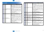
Service Mode > FAX > List of NCU > BUSY TONE1
Service Mode > FAX > List of NCU > BUSY TONE1
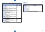
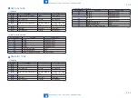
(2) Numeric value parameter
Parameter No.
Function
Setting range
01;
T0 timer
0 to 9999 (x10ms)
02;
T1 timer
0 to 9999 (x10ms)
03;
T2 timer
0 to 9999 (x10ms)
04;
T3 timer
0 to 9999 (x10ms)
05;
T4 timer
0 to 9999 (x10ms)
06;
Signal detection table
0 to 16
07;
Signal detection level
0 to 7
08;
Number of valid tone detection
0 to 9999 (times)
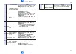
■
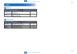
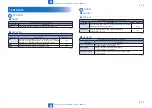
2nd DIAL TONE
(1) Bit switch
Bit No.
Function
1
0
Bit 0
Frequency detection method
Modem
Tonal counter
Bit 1
Bit 2
Signal frequency
Changed
Not changed
Bit 3
Bit 4
Judgment of intermittent signal
Start from valid ON
signal
Start from either valid
ON signal or OFF signal
Bit 5
Bit 6
Signal form
Continuous
Intermittent
Bit 7
Signal detection
Detected
Not detected
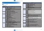
(2) Numeric value parameter
Parameter No.
Function
Setting range
01;
T0 timer
0 to 9999 (x10ms)
02;
T1 timer
0 to 9999 (x10ms)
03;
T2 timer
0 to 9999 (x10ms)
04;
T3 timer
0 to 9999 (x10ms)
05;
T4 timer
0 to 9999 (x10ms)
06;
Signal detection table
0 to 16
07;
Signal detection level
0 to 7
08;
Number of valid tone detection
0 to 9999 (times)
T-8-25
T-8-26
T-8-27
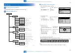
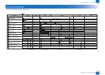
■
BUSY TONE0
(1) Bit switch
Bit No.
Function
1
0
Bit 0
Bit 1
Bit 2
Signal frequency
Changed
Not changed
Bit 3
Bit 4
Judgment of intermittent signal
Start from valid ON
signal
Start from either valid
ON signal or OFF signal
Bit 5
Bit 6
Signal form
Continuous
Intermittent
Bit 7
Signal detection
Detected
Not detected
(2) Numeric value parameter
Parameter No.
Function
Setting range
01;
02;
T1 timer
0 to 9999 (x10ms)
03;
T2 timer
0 to 9999 (x10ms)
04;
T3 timer
0 to 9999 (x10ms)
05;
T4 timer
0 to 9999 (x10ms)
06;
Signal detection table
0 to 16
07;
Signal detection level
0 to 7
08;
Number of valid tone detection
0 to 9999 (times)
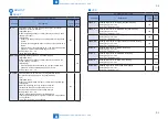
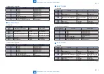
■
BUSY TONE1
(1) Bit switch
Bit No.
Function
1
0
Bit 0
Bit 1
Bit 2
Signal frequency
Changed
Not changed
Bit 3
RBT signal detection
Detected
Not detected
Bit 4
Judgment of intermittent signal
Start from valid ON
signal
Start from either valid
ON signal or OFF signal
Bit 5
RBT signal check cycle
1 cycle
1/2 cycle
Bit 6
Signal form
Continuous
Intermittent
Bit 7
Signal detection
Detected
Not detected
T-8-28
T-8-29
T-8-30
Содержание MF4500 Series
Страница 15: ...1 1 Product Overview Product Overview Product Lineups Features Product Specifications Name of Parts ...
Страница 222: ...5 5 Adjustment Adjustment Mechanical Adjustment ...
Страница 224: ...6 6 Trouble Shooting Trouble Shooting Test Print Trouble Shooting Items Version Upgrade ...
Страница 230: ...7 7 Error Codes Error Codes Overview Error Codes ...
Страница 234: ...8 8 Service Mode Service Mode Overview COPIER FEEDER FAX TESTMODE ...
Страница 251: ... Service Tools Solvent Oil List General Circuit Diagram General Timing Chart Appendix ...


