


4
4
4-148
4-148
Disassembly/Assembly > Pickup And Feeding System > Removing the Pickup Solenoid Duplex models (MF4580dn/MF4570dn/MF4550d/MF4553d/MF4554d/D550/D520)
Disassembly/Assembly > Pickup And Feeding System > Removing the Pickup Solenoid Duplex models (MF4580dn/MF4570dn/MF4550d/MF4553d/MF4554d/D550/D520)
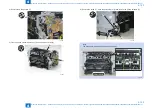
Before Removing the Pickup Solenoid
Duplex models (MF4580dn/MF4570dn/MF4550d/
MF4553d/MF4554d/D550/D520)
1) Remove the left cover. (Duplex models) (Refer to page 4-31)
2-1) Remove the DADF unit and reader unit. (models with DADF) (Refer to page 4-40)
2-2) Remove the SADF unit and reader unit. (models with SADF) (Refer to page 4-53)
2-3) Remove the copyboard cover and reader unit. (models with copyboard) (Refer to page
3) Remove the right cover. (Duplex models) (Refer to page 4-33)
4) Remove the front cover unit. (Refer to page 4-35)
5) Remove the upper cover. (Refer to page 4-35)
6) Remove the duplex feed unit. (Duplex models) (Refer to page 4-155)
7-1) Remove the main controller PCB. (models with FAX) (Refer to page 4-99)
7-2) Remove the main controller PCB. (models without FAX or NET) (Refer to page 4-100)
8-1) Remove the FAX-NCU PCB. (100V models with FAX) (Refer to page 4-102)
8-2) Remove the FAX-NCU PCB. (120V/220V models with FAX) (Refer to page 4-103)
9) Remove the pseudo CI board PCB. (100V models with FAX) (Refer to page 4-103)
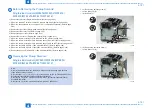
Removing the Pickup Solenoid
Duplex models (MF4580dn/MF4570dn/MF4550d/
MF4553d/MF4554d/D550/D520)
Note:
Refer to the below steps when removing a main controller mounting plate because
steps differ according to model.
Refer to steps 1-1-1), 1-1-2) and 1-1-3) for the models with FAX (MF4580dn/MF4570dn/
MF4550d/MF4553d/MF4554d/MF4450/MF4452/MF4453)
Refer to step 1-2) for the models without FAX or NET (MF4430/MF4550d/MF4410/
MF4412/D550/D520)
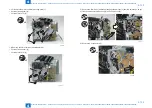
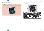
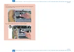
1-1-1) Remove the harness guide [1].
• 1 screw (black TP) [2]
• 1 wire saddle [3]
[1]
[2]
[3]
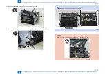
1-1-2) Remove the anti-noise plate [1].
• 1 screw (black TP) [2]
[2]
[1]
F-4-372
F-4-373
Содержание MF4500 Series
Страница 15: ...1 1 Product Overview Product Overview Product Lineups Features Product Specifications Name of Parts ...
Страница 222: ...5 5 Adjustment Adjustment Mechanical Adjustment ...
Страница 224: ...6 6 Trouble Shooting Trouble Shooting Test Print Trouble Shooting Items Version Upgrade ...
Страница 230: ...7 7 Error Codes Error Codes Overview Error Codes ...
Страница 234: ...8 8 Service Mode Service Mode Overview COPIER FEEDER FAX TESTMODE ...
Страница 251: ... Service Tools Solvent Oil List General Circuit Diagram General Timing Chart Appendix ...


